Última actualización: septiembre 21, 2021
- ID 002
- ID 012
- ID 211
- ID 120
- ID 011
- ID 021
ITN Final Skills Exam (PTSA) – ID: 002 – Last Updated: Aug 2021
ITN (Version 7.00) Final PT Skills Assessment (PTSA) Exam Answers
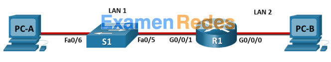
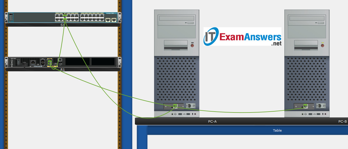
Topology
Device Names Table
You will receive one of three possible scenarios. In order to use the logical topology diagram that is provided with the instructions, use the device names in the Device Names Table.
| Topology Diagram Name | Your Scenario Name |
|---|---|
| R1 | R1 |
| S1 | S1 |
| PC-A | PC-A |
| PC-B | PC-B |
Addressing Requirements Table
| Item | Requirements |
|---|---|
| Network Address | 192.168.10.0/24 |
| LAN 1 subnet host requirements | 100 |
| LAN 2 subnet host requirements | 50 |
| R1 G0/0/1 | First host address in LAN 1 subnet |
| R1 G0/0/0 | First host address in LAN 2 subnet |
| S1 SVI | Second host address in LAN 1 subnet |
| PC-A | Last host address in LAN 1 subnet |
| PC-B | Last host address in LAN 2 subnet |
ITN Final PT Skills Assessment (PTSA)
- Do not use the browser Back button or close or reload any exam windows during the exam.
- Do not close Packet Tracer when you are done. It will close automatically.
- Click the Submit Assessment button in the browser window to submit your work.
Assessment Objectives
- Part 1: Build the Network
- Part 2: Develop an IP Addressing Scheme
- Part 3: Configure Basic Device Settings
- Part 4: Configure Security Settings on R1 and S1
- Part 5: Configure the Hosts and Verify Connectivity
Instructions
In this assessment you will configure the R1 router and S1 switch, as you have done in the activities in this course. You will also connect two PCs using a switch and a router that are in the main wiring closet. You will subnet the 192.168.10.0/24 network to provide IPv4 addresses for two subnets that will support the required number of hosts. The larger subnet (LAN 1) requires 100 hosts and the smaller subnet (LAN 2) requires 50 hosts.
No subnet calculators may be used.
Part 1: Build the Network
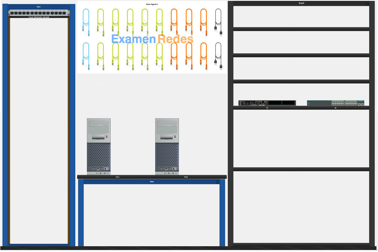
a. Build the network according to the logical topology by placing the required equipment in the wiring closet equipment rack.
b. Cable the network devices in the closet as shown in the topology diagram.
c. Connect the hosts as shown in the topology diagram.
Part 2: Develop an IP Addressing Scheme
In this part of the assessment you will develop an IP addressing scheme. You will subnet an IPv4 network to create two subnets with the required number of hosts. You will also subnet an IPv6 network. You will then assign the addresses according to the requirements below.
Work with the following information:
- IPv4 Network: 192.168.10.0/24
- Required number of hosts in IPv4 LAN 1: 100
- Required number of hosts in IPv4 LAN 2: 50
a. Record your subnet assignments according to the following requirements.
1) Assign the first IPv4 address of each subnet to a router interface
- LAN 1 is hosted on R1 G0/0/1
- LAN 2 is hosted on R1 G0/0/0
2) Assign the last IPv4 address of each subnet to the PC NIC.
3) Assign the second IPv4 address of LAN 1 to S1 SVI.
Part 3: Configure Basic Device Settings
Network devices must be configured over a direct console connection.
Step 1: Configure Basic Settings
a. Disable DNS lookup on R1 and S1
b. Configure router hostname using the name R1.
c. Configure switch hostname using the name S1.
d. Configure an appropriate banner on R1 and S1.
e. Allow console logins with the password C@nsPassw!
Step 2: Configure Interfaces
a. Configure R1 G0/0/0 and G0/0/1 interfaces using the addressing from the previous part of this assessment:
- Interface description
- IPv4 address / subnet mask
b. Configure the S1 VLAN 1 SVI interface using the addressing from the previous part of this assessment:
- Interface description
- IPv4 address / subnet mask
- The switch should be reachable from devices on other networks.
Part 4: Configure Security Settings on R1 and S1
Step 1: Configure enhanced password security
a. Configure NoOneShouldKnow as the encrypted privileged EXEC password
b. Encrypt all plaintext passwords
c. Set minimum password length to 10 on R1.
Step 2: Configure SSH on R1 and S1
a. Configure netsec.com as the domain name
b. Configure a local user netadmin with the encrypted password Ci$co12345
c. Set login on vty lines to use local database.
d. Configure the vty lines to accept SSH access only.
e. Generate an RSA crypto key using 1024 bits modulus.
Step 3: Secure switch ports on S1
a. Shut down all unused ports on S1.
b. Enter descriptions for all unused switch ports to indicate that they are intentionally shutdown.
Part 5: Configure the Hosts and Verify Connectivity
Configure both hosts with the IPv4 addresses that were assigned in Part 2 of this assessment.
ID: 002
Answers Key – 100% Score
Part 1: Build the Network
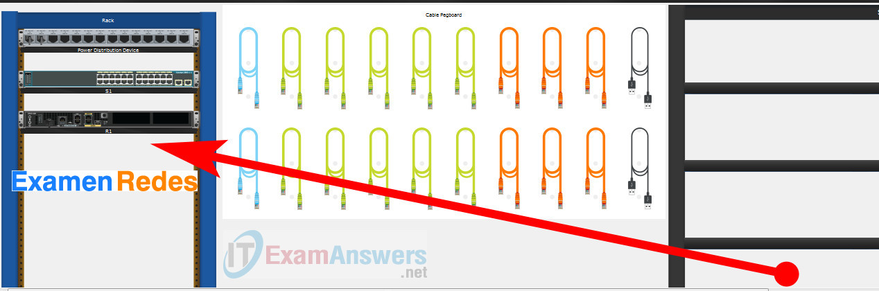
Placing Switch S1 and Router R1 to wiring closet equipment rack.
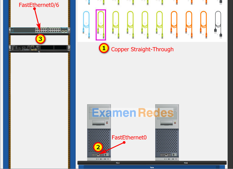
Using Copper Straight-Through cable to connect PC-A (FastEthernet0 port) and S1 (FastEthernet0/6 port)
Same as above, using Copper Straight-Through cable to connect all devices as shown in the topology diagram.
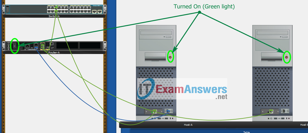
Turn-on PCs and Router R1
Part 2: Develop an IP Addressing Scheme
| Item | Requirements | IPv4 Address |
|---|---|---|
| Network Address | 192.168.10.0/24 | |
| LAN 1 subnet host requirements | 100 | 192.168.10.0/25 SM: 255.255.255.128 |
| LAN 2 subnet host requirements | 50 | 192.168.10.128/26 SM: 255.255.255.192 |
| R1 G0/0/1 | First host address in LAN 1 subnet | 192.168.10.1 |
| R1 G0/0/0 | First host address in LAN 2 subnet | 192.168.10.129 |
| S1 SVI | Second host address in LAN 1 subnet | 192.168.10.2 |
| PC-A | Last host address in LAN 1 subnet | 192.168.10.126 |
| PC-B | Last host address in LAN 2 subnet | 192.168.10.190 |
Configuration for router R1
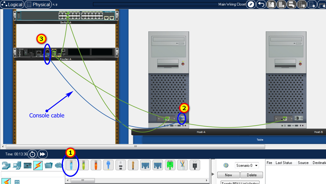
Using line console to connect PC-A and Router R1
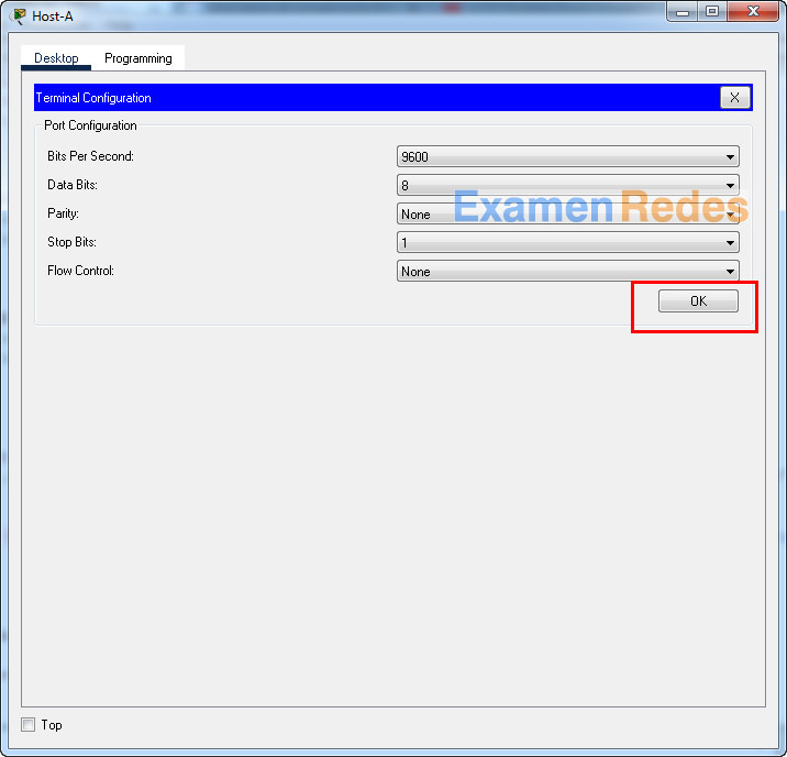
Click to PC-A –> Terminal app –> click OK
Router R1 configuration script
enable
configure terminal
no ip domain-lookup
hostname R1
banner motd #Unauthorized access to this device is prohibited!#

interface g0/0/0
description Connect to Subnet B
ip address 192.168.10.129 255.255.255.192
no shutdown
exit

interface g0/0/1
description Connect to Subnet A
ip address 192.168.10.1 255.255.255.128
no shutdown
exit

enable secret NoOneShouldKnow
service password-encryption
security passwords min-length 10

ip domain-name netsec.com
username netadmin secret Ci$co12345

line console 0
password C@nsPassw!
login
exit

line vty 0 15
transport input ssh
login local
exit

crypto key generate rsa
1024
exit
copy running-config startup-config
Configuration for Switch S1
Then, using Console cable to connect User-B and Switch
To show Console port on Switch, Right click Switch –> Inspect Rear –> Console port
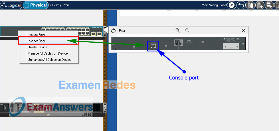
Switch S1 configuration script
enable
configure terminal
no ip domain-lookup
hostname S1
banner motd #Unauthorized access to this device is prohibited!#

interface vlan 1
description Switch Subnet A
ip address 192.168.10.2 255.255.255.128
no shutdown
exit

ip default-gateway 192.168.10.1

enable secret NoOneShouldKnow
service password-encryption

ip domain-name netsec.com
username netadmin secret Ci$co12345

line console 0
password C@nsPassw!
login
exit

line vty 0 15
transport input ssh
login local
exit

crypto key generate rsa
1024

int range f0/1 - 4, f0/7 - 24, g0/1 - 2
description Unused switch ports
shutdown

end
copy running-config startup-config
Part 5: Configure the Hosts and Verify Connectivity
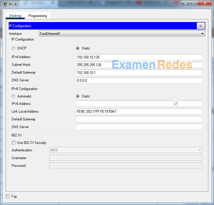
On PCs, go to Desktop tab –> IP Configuration menu
| PC-A Network Configuration | |
|---|---|
| IPv4 Address | 192.168.10.126 |
| Subnet Mask | 255.255.255.128 |
| IPv4 Default Gateway | 192.168.10.1 |
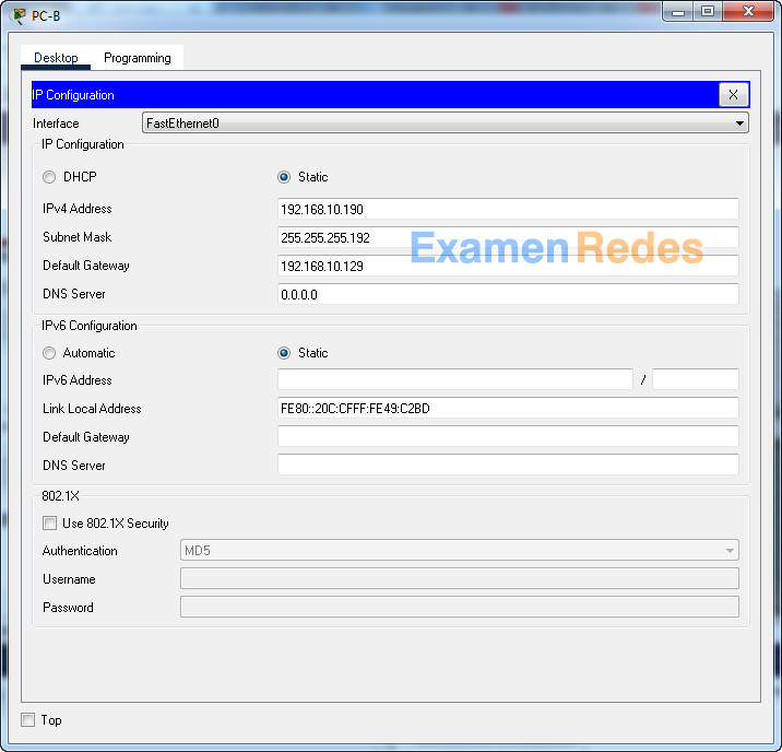
| PC-B Network Configuration | |
|---|---|
| IPv4 Address | 192.168.10.190 |
| Subnet Mask | 255.255.255.192 |
| IPv4 Default Gateway | 192.168.10.129 |
ITN Final Skills Exam (PTSA)
ITN (Version 7.00) Final PT Skills Assessment (PTSA) Exam Answers
Topology
Device Names Table
You will receive one of three possible scenarios. In order to use the logical topology diagram that is provided with the instructions, use the device names in the Device Names Table.
| Topology Diagram Name | Your Scenario Name |
|---|---|
| R1 | Central-RT |
| S1 | Central-SW |
| PC-A | User-A |
| PC-B | User-B |
Addressing Requirements Table
| Item | Requirements |
|---|---|
| Network Address | 192.168.10.0/24 |
| LAN 1 subnet host requirements | 100 |
| LAN 2 subnet host requirements | 50 |
| Central-RT G0/0/1 | First host address in LAN 1 subnet |
| Central-RT G0/0/0 | First host address in LAN 2 subnet |
| Central-SW SVI | Second host address in LAN 1 subnet |
| User-A | Last host address in LAN 1 subnet |
| User-B | Last host address in LAN 2 subnet |
ITN Final PT Skills Assessment (PTSA)
- Do not use the browser Back button or close or reload any exam windows during the exam.
- Do not close Packet Tracer when you are done. It will close automatically.
- Click the Submit Assessment button in the browser window to submit your work.
Assessment Objectives
- Part 1: Build the Network
- Part 2: Develop an IP Addressing Scheme
- Part 3: Configure Basic Device Settings
- Part 4: Configure Security Settings on Central-RT and Central-SW
- Part 5: Configure the Hosts and Verify Connectivity
Instructions
In this assessment you will configure the Central-RT router and Central-SW switch, as you have done in the activities in this course. You will also connect two PCs using a switch and a router that are in the main wiring closet. You will subnet the 192.168.10.0/24 network to provide IPv4 addresses for two subnets that will support the required number of hosts. The larger subnet (LAN 1) requires 100 hosts and the smaller subnet (LAN 2) requires 50 hosts.
No subnet calculators may be used.
Part 1: Build the Network
a. Build the network according to the logical topology by placing the required equipment in the wiring closet equipment rack.
b. Cable the network devices in the closet as shown in the topology diagram.
c. Connect the hosts as shown in the topology diagram.
Part 2: Develop an IP Addressing Scheme
In this part of the assessment you will develop an IP addressing scheme. You will subnet an IPv4 network to create two subnets with the required number of hosts. You will also subnet an IPv6 network. You will then assign the addresses according to the requirements below.
Work with the following information:
- IPv4 Network: 192.168.10.0/24
- Required number of hosts in IPv4 LAN 1: 100
- Required number of hosts in IPv4 LAN 2: 50
a. Record your subnet assignments according to the following requirements.
1) Assign the first IPv4 address of each subnet to a router interface
- LAN 1 is hosted on Central-RT G0/0/1
- LAN 2 is hosted on Central-RT G0/0/0
2) Assign the last IPv4 address of each subnet to the PC NIC.
3) Assign the second IPv4 address of LAN 1 to Central-SW SVI.
Part 3: Configure Basic Device Settings
Network devices must be configured over a direct console connection.
Step 1: Configure Basic Settings
a. Disable DNS lookup on Central-RT and Central-SW
b. Configure router hostname using the name Central-RT.
c. Configure switch hostname using the name Central-SW.
d. Configure an appropriate banner on Central-RT and Central-SW.
e. Allow console logins with the password C@nsPassw!
Step 2: Configure Interfaces
a. Configure Central-RT G0/0/0 and G0/0/1 interfaces using the addressing from the previous part of this assessment:
- Interface description
- IPv4 address / subnet mask
b. Configure the Central-SW VLAN 1 SVI interface using the addressing from the previous part of this assessment:
- Interface description
- IPv4 address / subnet mask
- The switch should be reachable from devices on other networks.
Part 4: Configure Security Settings on Central-RT and Central-SW
Step 1: Configure enhanced password security
a. Configure NoOneShouldKnow as the encrypted privileged EXEC password
b. Encrypt all plaintext passwords
c. Set minimum password length to 10 on Central-RT.
Step 2: Configure SSH on Central-RT and Central-SW
a. Configure netsec.com as the domain name
b. Configure a local user netadmin with the encrypted password Ci$co12345
c. Set login on vty lines to use local database.
d. Configure the vty lines to accept SSH access only.
e. Generate an RSA crypto key using 1024 bits modulus.
Step 3: Secure switch ports on Central-SW
a. Shut down all unused ports on Central-SW.
b. Enter descriptions for all unused switch ports to indicate that they are intentionally shutdown.
Part 5: Configure the Hosts and Verify Connectivity
Configure both hosts with the IPv4 addresses that were assigned in Part 2 of this assessment.
ID: 012
Answers Key
Part 1: Build the Network
Placing Switch Central-SW and Router Central-RT to wiring closet equipment rack.
Using Copper Straight-Through cable to connect User-A (FastEthernet0 port) and Central-SW (FastEthernet0/6 port)
Same as above, using Copper Straight-Through cable to connect all devices as shown in the topology diagram.
Turn-on PCs and Router Central-RT
Part 2: Develop an IP Addressing Scheme
| Item | Requirements | IPv4 Address |
|---|---|---|
| Network Address | 192.168.10.0/24 | |
| LAN 1 subnet host requirements | 100 | 192.168.10.0/25 SM: 255.255.255.128 |
| LAN 2 subnet host requirements | 50 | 192.168.10.128/26 SM: 255.255.255.192 |
| Central-RT G0/0/1 | First host address in LAN 1 subnet | 192.168.10.1 |
| Central-RT G0/0/0 | First host address in LAN 2 subnet | 192.168.10.129 |
| Central-SW SVI | Second host address in LAN 1 subnet | 192.168.10.2 |
| User-A | Last host address in LAN 1 subnet | 192.168.10.126 |
| User-B | Last host address in LAN 2 subnet | 192.168.10.190 |
Using line console to connect User-A and Router
Click to User-A –> Terminal app –> click OK
Router Central-RT configuration script
enable
configure terminal
no ip domain-lookup
hostname Central-RT
banner motd #Unauthorized access to this device is prohibited!#

interface g0/0/0
description Connect to Subnet B
ip address 192.168.10.129 255.255.255.192
no shutdown
exit

interface g0/0/1
description Connect to Subnet A
ip address 192.168.10.1 255.255.255.128
no shutdown
exit

enable secret NoOneShouldKnow
service password-encryption
security passwords min-length 10

ip domain-name netsec.com
username netadmin secret Ci$co12345

line console 0
password C@nsPassw!
login
exit

line vty 0 15
transport input ssh
login local
exit

crypto key generate rsa
1024
exit
copy running-config startup-config
Configuration for Switch Central-SW
Then, using Console cable to connect User-B and Switch
To show Console port on Switch, Right click Switch –> Inspect Rear –> Console port
Switch Central-SW configuration script
enable
configure terminal
no ip domain-lookup
hostname Central-SW
banner motd #Unauthorized access to this device is prohibited!#

interface vlan 1
description Switch Subnet A
ip address 192.168.10.2 255.255.255.128
no shutdown
exit

ip default-gateway 192.168.10.1

enable secret NoOneShouldKnow
service password-encryption

ip domain-name netsec.com
username netadmin secret Ci$co12345

line console 0
password C@nsPassw!
login
exit

line vty 0 15
transport input ssh
login local
exit

crypto key generate rsa
1024

int range f0/1 - 4, f0/7 - 24, g0/1 - 2
description Unused switch ports
shutdown

end
copy running-config startup-config
Part 5: Configure the Hosts and Verify Connectivity
On PCs, go to Desktop tab –> IP Configuration menu
| PC-A Network Configuration | |
|---|---|
| IPv4 Address | 192.168.10.126 |
| Subnet Mask | 255.255.255.128 |
| IPv4 Default Gateway | 192.168.10.1 |
| PC-B Network Configuration | |
|---|---|
| IPv4 Address | 192.168.10.190 |
| Subnet Mask | 255.255.255.192 |
| IPv4 Default Gateway | 192.168.10.129 |
ITN Final Skills Exam (PTSA)
ITN (Version 7.00) Final PT Skills Assessment (PTSA) Exam Answers
Topology
Device Names Table
You will receive one of three possible scenarios. In order to use the logical topology diagram that is provided with the instructions, use the device names in the Device Names Table.
| Topology Diagram Name | Your Scenario Name |
|---|---|
| R1 | Central-RT |
| S1 | Central-SW |
| PC-A | User-A |
| PC-B | User-B |
Addressing Requirements Table
| Item | Requirements |
|---|---|
| Network Address | 209.165.201.0/24 |
| LAN 1 subnet host requirements | 29 |
| LAN 2 subnet host requirements | 17 |
| Central-RT G0/0/1 | First host address in LAN 1 subnet |
| Central-RT G0/0/0 | First host address in LAN 2 subnet |
| Central-SW SVI | Second host address in LAN 1 subnet |
| User-A | Last host address in LAN 1 subnet |
| User-B | Last host address in LAN 2 subnet |
ITN Final PT Skills Assessment (PTSA)
- Do not use the browser Back button or close or reload any exam windows during the exam.
- Do not close Packet Tracer when you are done. It will close automatically.
- Click the Submit Assessment button in the browser window to submit your work.
Assessment Objectives
- Part 1: Build the Network
- Part 2: Develop an IP Addressing Scheme
- Part 3: Configure Basic Device Settings
- Part 4: Configure Security Settings on Central-RT and Central-SW
- Part 5: Configure the Hosts and Verify Connectivity
Instructions
In this assessment you will configure the Central-RT router and Central-SW switch, as you have done in the activities in this course. You will also connect two PCs using a switch and a router that are in the main wiring closet. You will subnet the 209.165.201.0/24 network to provide IPv4 addresses for two subnets that will support the required number of hosts. The larger subnet (LAN 1) requires 29 hosts and the smaller subnet (LAN 2) requires 17 hosts.
No subnet calculators may be used.
Part 1: Build the Network
a. Build the network according to the logical topology by placing the required equipment in the wiring closet equipment rack.
b. Cable the network devices in the closet as shown in the topology diagram.
c. Connect the hosts as shown in the topology diagram.
Part 2: Develop an IP Addressing Scheme
In this part of the assessment you will develop an IP addressing scheme. You will subnet an IPv4 network to create two subnets with the required number of hosts. You will also subnet an IPv6 network. You will then assign the addresses according to the requirements below.
Work with the following information:
- IPv4 Network: 209.165.201.0/24
- Required number of hosts in IPv4 LAN 1: 29
- Required number of hosts in IPv4 LAN 2: 17
a. Record your subnet assignments according to the following requirements.
1) Assign the first IPv4 address of each subnet to a router interface
- LAN 1 is hosted on Central-RT G0/0/1
- LAN 2 is hosted on Central-RT G0/0/0
2) Assign the last IPv4 address of each subnet to the PC NIC.
3) Assign the second IPv4 address of LAN 1 to Central-SW SVI.
Part 3: Configure Basic Device Settings
Network devices must be configured over a direct console connection.
Step 1: Configure Basic Settings
a. Disable DNS lookup on Central-RT and Central-SW
b. Configure router hostname using the name Central-RT.
c. Configure switch hostname using the name Central-SW.
d. Configure an appropriate banner on Central-RT and Central-SW.
e. Allow console logins with the password C@nsPassw!
Step 2: Configure Interfaces
a. Configure Central-RT G0/0/0 and G0/0/1 interfaces using the addressing from the previous part of this assessment:
- Interface description
- IPv4 address / subnet mask
b. Configure the Central-SW VLAN 1 SVI interface using the addressing from the previous part of this assessment:
- Interface description
- IPv4 address / subnet mask
- The switch should be reachable from devices on other networks.
Part 4: Configure Security Settings on Central-RT and Central-SW
Step 1: Configure enhanced password security
a. Configure NoOneShouldKnow as the encrypted privileged EXEC password
b. Encrypt all plaintext passwords
c. Set minimum password length to 10 on Central-RT.
Step 2: Configure SSH on Central-RT and Central-SW
a. Configure netsec.com as the domain name
b. Configure a local user netadmin with the encrypted password Ci$co12345
c. Set login on vty lines to use local database.
d. Configure the vty lines to accept SSH access only.
e. Generate an RSA crypto key using 1024 bits modulus.
Step 3: Secure switch ports on Central-SW
a. Shut down all unused ports on Central-SW.
b. Enter descriptions for all unused switch ports to indicate that they are intentionally shutdown.
Part 5: Configure the Hosts and Verify Connectivity
Configure both hosts with the IPv4 addresses that were assigned in Part 2 of this assessment.
ID: 211
Answers Key – 100% Score
Part 1: Build the Network
Placing Switch Central-SW and Router Central-RT to wiring closet equipment rack.
Using Copper Straight-Through cable to connect User-A (FastEthernet0 port) and Central-SW (FastEthernet0/6 port)
Same as above, using Copper Straight-Through cable to connect all devices as shown in the topology diagram.
Turn-on PCs and Router Central-RT
Part 2: Develop an IP Addressing Scheme
| Item | Requirements | IPv4 Address |
|---|---|---|
| Network Address | 209.165.201.0/24 | |
| LAN 1 subnet host requirements | 29 | 209.165.201.0/27 SM: 255.255.255.224 |
| LAN 2 subnet host requirements | 17 | 209.165.201.32/27 SM: 255.255.255.224 |
| Central-RT G0/0/1 | First host address in LAN 1 subnet | 209.165.201.1 |
| Central-RT G0/0/0 | First host address in LAN 2 subnet | 209.165.201.33 |
| Central-SW SVI | Second host address in LAN 1 subnet | 209.165.201.2 |
| User-A | Last host address in LAN 1 subnet | 209.165.201.30 |
| User-B | Last host address in LAN 2 subnet | 209.165.201.62 |
Using line console to connect User-A and Router
Click to User-A –> Terminal app –> click OK
Router Central-RT configuration script
enable
configure terminal
no ip domain-lookup
hostname Central-RT
banner motd #Unauthorized access to this device is prohibited!#

interface g0/0/0
description Connect to Subnet B
ip address 209.165.201.33 255.255.255.224
no shutdown
exit

interface g0/0/1
description Connect to Subnet A
ip address 209.165.201.1 255.255.255.224
no shutdown
exit

enable secret NoOneShouldKnow
service password-encryption
security passwords min-length 10

ip domain-name netsec.com
username netadmin secret Ci$co12345

line console 0
password C@nsPassw!
login
exit

line vty 0 15
transport input ssh
login local
exit

crypto key generate rsa
1024
exit
copy running-config startup-config
Configuration for Switch Central-SW
Then, using Console cable to connect User-B and Switch
To show Console port on Switch, Right click Switch –> Inspect Rear –> Console port
Switch Central-SW configuration script
enable
configure terminal
no ip domain-lookup
hostname Central-SW
banner motd #Unauthorized access to this device is prohibited!#

interface vlan 1
description Switch Subnet A
ip address 209.165.201.2 255.255.255.224
no shutdown
exit

ip default-gateway 209.165.201.1

enable secret NoOneShouldKnow
service password-encryption

ip domain-name netsec.com
username netadmin secret Ci$co12345

line console 0
password C@nsPassw!
login
exit

line vty 0 15
transport input ssh
login local
exit

crypto key generate rsa
1024

int range f0/1 - 4, f0/7 - 24, g0/1 - 2
description Unused switch ports
shutdown

end
copy running-config startup-config
Part 5: Configure the Hosts and Verify Connectivity
On PCs, go to Desktop tab –> IP Configuration menu
| PC-A Network Configuration | |
|---|---|
| IPv4 Address | 209.165.201.30 |
| Subnet Mask | 255.255.255.224 |
| IPv4 Default Gateway | 209.165.201.1 |
| PC-B Network Configuration | |
|---|---|
| IPv4 Address | 209.165.201.62 |
| Subnet Mask | 255.255.255.224 |
| IPv4 Default Gateway | 209.165.201.33 |
ITN Final Skills Exam (PTSA)
ITN (Version 7.00) Final PT Skills Assessment (PTSA) Exam Answers
Topology
Device Names Table
You will receive one of three possible scenarios. In order to use the logical topology diagram that is provided with the instructions, use the device names in the Device Names Table.
| Topology Diagram Name | Your Scenario Name |
|---|---|
| R1 | Router-A |
| S1 | Switch-A |
| PC-A | Host-A |
| PC-B | Host-B |
Addressing Requirements Table
| Item | Requirements |
|---|---|
| Network Address | 172.16.1.0/24 |
| LAN 1 subnet host requirements | 60 |
| LAN 2 subnet host requirements | 20 |
| Router-A G0/0/1 | First host address in LAN 1 subnet |
| Router-A G0/0/0 | First host address in LAN 2 subnet |
| Switch-A SVI | Second host address in LAN 1 subnet |
| User-A | Last host address in LAN 1 subnet |
| User-B | Last host address in LAN 2 subnet |
ITN Final PT Skills Assessment (PTSA)
- Do not use the browser Back button or close or reload any exam windows during the exam.
- Do not close Packet Tracer when you are done. It will close automatically.
- Click the Submit Assessment button in the browser window to submit your work.
Assessment Objectives
- Part 1: Build the Network
- Part 2: Develop an IP Addressing Scheme
- Part 3: Configure Basic Device Settings
- Part 4: Configure Security Settings on Router-A and Switch-A
- Part 5: Configure the Hosts and Verify Connectivity
Instructions
In this assessment you will configure the Router-A router and Switch-A switch, as you have done in the activities in this course. You will also connect two PCs using a switch and a router that are in the main wiring closet. You will subnet the 172.16.1.0/24 network to provide IPv4 addresses for two subnets that will support the required number of hosts. The larger subnet (LAN 1) requires 60 hosts and the smaller subnet (LAN 2) requires 20 hosts.
No subnet calculators may be used.
Part 1: Build the Network
a. Build the network according to the logical topology by placing the required equipment in the wiring closet equipment rack.
b. Cable the network devices in the closet as shown in the topology diagram.
c. Connect the hosts as shown in the topology diagram.
Part 2: Develop an IP Addressing Scheme
In this part of the assessment you will develop an IP addressing scheme. You will subnet an IPv4 network to create two subnets with the required number of hosts. You will also subnet an IPv6 network. You will then assign the addresses according to the requirements below.
Work with the following information:
- IPv4 Network: 172.16.1.0/24
- Required number of hosts in IPv4 LAN 1: 60
- Required number of hosts in IPv4 LAN 2: 20
a. Record your subnet assignments according to the following requirements.
1) Assign the first IPv4 address of each subnet to a router interface
- LAN 1 is hosted on Router-A G0/0/1
- LAN 2 is hosted on Router-A G0/0/0
2) Assign the last IPv4 address of each subnet to the PC NIC.
3) Assign the second IPv4 address of LAN 1 to Switch-A SVI.
Part 3: Configure Basic Device Settings
Network devices must be configured over a direct console connection.
Step 1: Configure Basic Settings
a. Disable DNS lookup on Router-A and Switch-A
b. Configure router hostname using the name Router-A.
c. Configure switch hostname using the name Switch-A.
d. Configure an appropriate banner on Router-A and Switch-A.
e. Allow console logins with the password C@nsPassw!
Step 2: Configure Interfaces
a. Configure Router-A G0/0/0 and G0/0/1 interfaces using the addressing from the previous part of this assessment:
- Interface description
- IPv4 address / subnet mask
b. Configure the Switch-A VLAN 1 SVI interface using the addressing from the previous part of this assessment:
- Interface description
- IPv4 address / subnet mask
- The switch should be reachable from devices on other networks.
Part 4: Configure Security Settings on Router-A and Switch-A
Step 1: Configure enhanced password security
a. Configure NoOneShouldKnow as the encrypted privileged EXEC password
b. Encrypt all plaintext passwords
c. Set minimum password length to 10 on Router-A.
Step 2: Configure SSH on Router-A and Switch-A
a. Configure netsec.com as the domain name
b. Configure a local user netadmin with the encrypted password Ci$co12345
c. Set login on vty lines to use local database.
d. Configure the vty lines to accept SSH access only.
e. Generate an RSA crypto key using 1024 bits modulus.
Step 3: Secure switch ports on Switch-A
a. Shut down all unused ports on Switch-A.
b. Enter descriptions for all unused switch ports to indicate that they are intentionally shutdown.
Part 5: Configure the Hosts and Verify Connectivity
Configure both hosts with the IPv4 addresses that were assigned in Part 2 of this assessment.
ID: 120
Answers Key – 100% Score
Part 1: Build the Network
Placing Switch Switch-A and Router Router-A to wiring closet equipment rack.
Using Copper Straight-Through cable to connect User-A (FastEthernet0 port) and Switch-A (FastEthernet0/6 port)
Same as above, using Copper Straight-Through cable to connect all devices as shown in the topology diagram.
Turn-on PCs and Router Router-A
Part 2: Develop an IP Addressing Scheme
| Item | Requirements | IPv4 Address |
|---|---|---|
| Network Address | 172.16.1.0/24 | |
| LAN 1 subnet host requirements | 60 | 172.16.1.0/26 SM: 255.255.255.192 |
| LAN 2 subnet host requirements | 20 | 172.16.1.64/27 SM: 255.255.255.224 |
| Router-A G0/0/1 | First host address in LAN 1 subnet | 172.16.1.1 |
| Router-A G0/0/0 | First host address in LAN 2 subnet | 172.16.1.65 |
| Switch-A SVI | Second host address in LAN 1 subnet | 172.16.1.2 |
| User-A | Last host address in LAN 1 subnet | 172.16.1.62 |
| User-B | Last host address in LAN 2 subnet | 172.16.1.94 |
Using line console to connect User-A and Router
Click to User-A –> Terminal app –> click OK
Router Router-A configuration script
enable
configure terminal
no ip domain-lookup
hostname Router-A
banner motd #Unauthorized access to this device is prohibited!#

interface g0/0/0
description Connect to Subnet B
ip address 172.16.1.65 255.255.255.224
no shutdown
exit

interface g0/0/1
description Connect to Subnet A
ip address 172.16.1.1 255.255.255.192
no shutdown
exit

enable secret NoOneShouldKnow
service password-encryption
security passwords min-length 10

ip domain-name netsec.com
username netadmin secret Ci$co12345

line console 0
password C@nsPassw!
login
exit

line vty 0 15
transport input ssh
login local
exit

crypto key generate rsa
1024
exit
copy running-config startup-config
Configuration for Switch-A
Then, using Console cable to connect User-B and Switch
To show Console port on Switch, Right click Switch –> Inspect Rear –> Console port
Switch Switch-A configuration script
enable
configure terminal
no ip domain-lookup
hostname Switch-A
banner motd #Unauthorized access to this device is prohibited!#

interface vlan 1
description Switch Subnet A
ip address 172.16.1.2 255.255.255.192
no shutdown
exit

ip default-gateway 172.16.1.1

enable secret NoOneShouldKnow
service password-encryption

ip domain-name netsec.com
username netadmin secret Ci$co12345

line console 0
password C@nsPassw!
login
exit

line vty 0 15
transport input ssh
login local
exit

crypto key generate rsa
1024

int range f0/1 - 4, f0/7 - 24, g0/1 - 2
description Unused switch ports
shutdown

end
copy running-config startup-config
Part 5: Configure the Hosts and Verify Connectivity
On PCs, go to Desktop tab –> IP Configuration menu
| PC-A Network Configuration | |
|---|---|
| IPv4 Address | 172.16.1.62 |
| Subnet Mask | 255.255.255.192 |
| IPv4 Default Gateway | 172.16.1.1 |
| PC-B Network Configuration | |
|---|---|
| IPv4 Address | 172.16.1.94 |
| Subnet Mask | 255.255.255.224 |
| IPv4 Default Gateway | 172.16.1.65 |
ITN Final Skills Exam (PTSA)
ITN (Version 7.00) Final PT Skills Assessment (PTSA) Exam Answers
Topology
Device Names Table
You will receive one of three possible scenarios. In order to use the logical topology diagram that is provided with the instructions, use the device names in the Device Names Table.
| Topology Diagram Name | Your Scenario Name |
|---|---|
| R1 | Central-RT |
| S1 | Central-SW |
| PC-A | User-A |
| PC-B | User-B |
Addressing Requirements Table
| Item | Requirements |
|---|---|
| Network Address | 192.168.10.0/24 |
| LAN 1 subnet host requirements | 100 |
| LAN 2 subnet host requirements | 50 |
| Central-RT G0/0/1 | First host address in LAN 1 subnet |
| Central-RT G0/0/0 | First host address in LAN 2 subnet |
| Central-SW SVI | Second host address in LAN 1 subnet |
| User-A | Last host address in LAN 1 subnet |
| User-B | Last host address in LAN 2 subnet |
ITN Final PT Skills Assessment (PTSA)
- Do not use the browser Back button or close or reload any exam windows during the exam.
- Do not close Packet Tracer when you are done. It will close automatically.
- Click the Submit Assessment button in the browser window to submit your work.
Assessment Objectives
- Part 1: Build the Network
- Part 2: Develop an IP Addressing Scheme
- Part 3: Configure Basic Device Settings
- Part 4: Configure Security Settings on Central-RT and Central-SW
- Part 5: Configure the Hosts and Verify Connectivity
Instructions
In this assessment you will configure the Central-RT router and Central-SW switch, as you have done in the activities in this course. You will also connect two PCs using a switch and a router that are in the main wiring closet. You will subnet the 192.168.10.0/24 network to provide IPv4 addresses for two subnets that will support the required number of hosts. The larger subnet (LAN 1) requires 100 hosts and the smaller subnet (LAN 2) requires 50 hosts.
No subnet calculators may be used.
Part 1: Build the Network
a. Build the network according to the logical topology by placing the required equipment in the wiring closet equipment rack.
b. Cable the network devices in the closet as shown in the topology diagram.
c. Connect the hosts as shown in the topology diagram.
Part 2: Develop an IP Addressing Scheme
In this part of the assessment you will develop an IP addressing scheme. You will subnet an IPv4 network to create two subnets with the required number of hosts. You will also subnet an IPv6 network. You will then assign the addresses according to the requirements below.
Work with the following information:
- IPv4 Network: 192.168.10.0/24
- Required number of hosts in IPv4 LAN 1: 100
- Required number of hosts in IPv4 LAN 2: 50
a. Record your subnet assignments according to the following requirements.
1) Assign the first IPv4 address of each subnet to a router interface
- LAN 1 is hosted on Central-RT G0/0/1
- LAN 2 is hosted on Central-RT G0/0/0
2) Assign the last IPv4 address of each subnet to the PC NIC.
3) Assign the second IPv4 address of LAN 1 to Central-SW SVI.
Part 3: Configure Basic Device Settings
Network devices must be configured over a direct console connection.
Step 1: Configure Basic Settings
a. Disable DNS lookup on Central-RT and Central-SW
b. Configure router hostname using the name Central-RT.
c. Configure switch hostname using the name Central-SW.
d. Configure an appropriate banner on Central-RT and Central-SW.
e. Allow console logins with the password C@nsPassw!
Step 2: Configure Interfaces
a. Configure Central-RT G0/0/0 and G0/0/1 interfaces using the addressing from the previous part of this assessment:
- Interface description
- IPv4 address / subnet mask
b. Configure the Central-SW VLAN 1 SVI interface using the addressing from the previous part of this assessment:
- Interface description
- IPv4 address / subnet mask
- The switch should be reachable from devices on other networks.
Part 4: Configure Security Settings on Central-RT and Central-SW
Step 1: Configure enhanced password security
a. Configure DontTellAnyone as the encrypted privileged EXEC password
b. Encrypt all plaintext passwords
c. Set minimum password length to 10 on Central-RT.
Step 2: Configure SSH on Central-RT and Central-SW
a. Configure netsec.com as the domain name
b. Configure a local user netadmin with the encrypted password Ci$co12345
c. Set login on vty lines to use local database.
d. Configure the vty lines to accept SSH access only.
e. Generate an RSA crypto key using 1024 bits modulus.
Step 3: Secure switch ports on Central-SW
a. Shut down all unused ports on Central-SW.
b. Enter descriptions for all unused switch ports to indicate that they are intentionally shutdown.
Part 5: Configure the Hosts and Verify Connectivity
Configure both hosts with the IPv4 addresses that were assigned in Part 2 of this assessment.
ID: 011
Answers Key
Part 1: Build the Network
Placing Switch Central-SW and Router Central-RT to wiring closet equipment rack.
Using Copper Straight-Through cable to connect User-A (FastEthernet0 port) and Central-SW (FastEthernet0/6 port)
Same as above, using Copper Straight-Through cable to connect all devices as shown in the topology diagram.
Turn-on PCs and Router Central-RT
Part 2: Develop an IP Addressing Scheme
| Item | Requirements | IPv4 Address |
|---|---|---|
| Network Address | 192.168.10.0/24 | |
| LAN 1 subnet host requirements | 100 | 192.168.10.0/25 SM: 255.255.255.128 |
| LAN 2 subnet host requirements | 50 | 192.168.10.128/26 SM: 255.255.255.192 |
| Central-RT G0/0/1 | First host address in LAN 1 subnet | 192.168.10.1 |
| Central-RT G0/0/0 | First host address in LAN 2 subnet | 192.168.10.129 |
| Central-SW SVI | Second host address in LAN 1 subnet | 192.168.10.2 |
| User-A | Last host address in LAN 1 subnet | 192.168.10.126 |
| User-B | Last host address in LAN 2 subnet | 192.168.10.190 |
Using line console to connect User-A and Router
Click to User-A –> Terminal app –> click OK
Router Central-RT configuration script
enable
configure terminal
no ip domain-lookup
hostname Central-RT
banner motd #Unauthorized access to this device is prohibited!#

interface g0/0/0
description Connect to Subnet B
ip address 192.168.10.129 255.255.255.192
no shutdown
exit

interface g0/0/1
description Connect to Subnet A
ip address 192.168.10.1 255.255.255.128
no shutdown
exit

enable secret DontTellAnyone
service password-encryption
security passwords min-length 10

ip domain-name netsec.com
username netadmin secret Ci$co12345

line console 0
password C@nsPassw!
login
exit

line vty 0 15
transport input ssh
login local
exit

crypto key generate rsa
1024
exit
copy running-config startup-config
Configuration for Switch Central-SW
Then, using Console cable to connect User-B and Switch
To show Console port on Switch, Right click Switch –> Inspect Rear –> Console port
Switch Central-SW configuration script
enable
configure terminal
no ip domain-lookup
hostname Central-SW
banner motd #Unauthorized access to this device is prohibited!#

interface vlan 1
description Switch Subnet A
ip address 192.168.10.2 255.255.255.128
no shutdown
exit

ip default-gateway 192.168.10.1

enable secret DontTellAnyone
service password-encryption

ip domain-name netsec.com
username netadmin secret Ci$co12345

line console 0
password C@nsPassw!
login
exit

line vty 0 15
transport input ssh
login local
exit

crypto key generate rsa
1024

int range f0/1 - 4, f0/7 - 24, g0/1 - 2
description Unused switch ports
shutdown

end
copy running-config startup-config
Part 5: Configure the Hosts and Verify Connectivity
On PCs, go to Desktop tab –> IP Configuration menu
| PC-A Network Configuration | |
|---|---|
| IPv4 Address | 192.168.10.126 |
| Subnet Mask | 255.255.255.128 |
| IPv4 Default Gateway | 192.168.10.1 |
| PC-B Network Configuration | |
|---|---|
| IPv4 Address | 192.168.10.190 |
| Subnet Mask | 255.255.255.192 |
| IPv4 Default Gateway | 192.168.10.129 |
ITN Final Skills Exam (PTSA)
ITN (Version 7.00) Final PT Skills Assessment (PTSA) Exam Answers
Topology
Device Names Table
You will receive one of three possible scenarios. In order to use the logical topology diagram that is provided with the instructions, use the device names in the Device Names Table.
| Topology Diagram Name | Your Scenario Name |
|---|---|
| R1 | Router-A |
| S1 | Switch-A |
| PC-A | Host-A |
| PC-B | Host-B |
Addressing Requirements Table
| Item | Requirements |
|---|---|
| Network Address | 192.168.10.0/24 |
| LAN 1 subnet host requirements | 100 |
| LAN 2 subnet host requirements | 50 |
| Router-A G0/0/1 | First host address in LAN 1 subnet |
| Router-A G0/0/0 | First host address in LAN 2 subnet |
| Switch-A SVI | Second host address in LAN 1 subnet |
| Host-A | Last host address in LAN 1 subnet |
| Host-B | Last host address in LAN 2 subnet |
ITN Final PT Skills Assessment (PTSA)
- Do not use the browser Back button or close or reload any exam windows during the exam.
- Do not close Packet Tracer when you are done. It will close automatically.
- Click the Submit Assessment button in the browser window to submit your work.
Assessment Objectives
- Part 1: Build the Network
- Part 2: Develop an IP Addressing Scheme
- Part 3: Configure Basic Device Settings
- Part 4: Configure Security Settings on Router-A and Switch-A
- Part 5: Configure the Hosts and Verify Connectivity
Instructions
In this assessment you will configure the Router-A router and Switch-A switch, as you have done in the activities in this course. You will also connect two PCs using a switch and a router that are in the main wiring closet. You will subnet the 192.168.10.0/24 network to provide IPv4 addresses for two subnets that will support the required number of hosts. The larger subnet (LAN 1) requires 100 hosts and the smaller subnet (LAN 2) requires 50 hosts.
No subnet calculators may be used.
Part 1: Build the Network
a. Build the network according to the logical topology by placing the required equipment in the wiring closet equipment rack.
b. Cable the network devices in the closet as shown in the topology diagram.
c. Connect the hosts as shown in the topology diagram.
Part 2: Develop an IP Addressing Scheme
In this part of the assessment you will develop an IP addressing scheme. You will subnet an IPv4 network to create two subnets with the required number of hosts. You will also subnet an IPv6 network. You will then assign the addresses according to the requirements below.
Work with the following information:
- IPv4 Network: 192.168.10.0/24
- Required number of hosts in IPv4 LAN 1: 100
- Required number of hosts in IPv4 LAN 2: 50
a. Record your subnet assignments according to the following requirements.
1) Assign the first IPv4 address of each subnet to a router interface
- LAN 1 is hosted on Router-A G0/0/1
- LAN 2 is hosted on Router-A G0/0/0
2) Assign the last IPv4 address of each subnet to the PC NIC.
3) Assign the second IPv4 address of LAN 1 to Switch-A SVI.
Part 3: Configure Basic Device Settings
Network devices must be configured over a direct console connection.
Step 1: Configure Basic Settings
a. Disable DNS lookup on Router-A and Switch-A
b. Configure router hostname using the name Router-A.
c. Configure switch hostname using the name Switch-A.
d. Configure an appropriate banner on Router-A and Switch-A.
e. Allow console logins with the password C@nsPassw!
Step 2: Configure Interfaces
a. Configure Router-A G0/0/0 and G0/0/1 interfaces using the addressing from the previous part of this assessment:
- Interface description
- IPv4 address / subnet mask
b. Configure the Switch-A VLAN 1 SVI interface using the addressing from the previous part of this assessment:
- Interface description
- IPv4 address / subnet mask
- The switch should be reachable from devices on other networks.
Part 4: Configure Security Settings on Router-A and Switch-A
Step 1: Configure enhanced password security
a. Configure DontTellAnyone as the encrypted privileged EXEC password
b. Encrypt all plaintext passwords
c. Set minimum password length to 10 on Router-A.
Step 2: Configure SSH on Router-A and Switch-A
a. Configure netsec.com as the domain name
b. Configure a local user netadmin with the encrypted password Ci$co12345
c. Set login on vty lines to use local database.
d. Configure the vty lines to accept SSH access only.
e. Generate an RSA crypto key using 1024 bits modulus.
Step 3: Secure switch ports on Switch-A
a. Shut down all unused ports on Switch-A.
b. Enter descriptions for all unused switch ports to indicate that they are intentionally shutdown.
Part 5: Configure the Hosts and Verify Connectivity
Configure both hosts with the IPv4 addresses that were assigned in Part 2 of this assessment.
ID: 021
Answers Key
Part 1: Build the Network
Placing Switch Switch-A and Router Router-A to wiring closet equipment rack.
Using Copper Straight-Through cable to connect Host-A (FastEthernet0 port) and Switch-A (FastEthernet0/6 port)
Same as above, using Copper Straight-Through cable to connect all devices as shown in the topology diagram.
Turn-on PCs and Router Router-A
Part 2: Develop an IP Addressing Scheme
| Item | Requirements | IPv4 Address |
|---|---|---|
| Network Address | 192.168.10.0/24 | |
| LAN 1 subnet host requirements | 100 | 192.168.10.0/25 SM: 255.255.255.128 |
| LAN 2 subnet host requirements | 50 | 192.168.10.128/26 SM: 255.255.255.192 |
| Router-A G0/0/1 | First host address in LAN 1 subnet | 192.168.10.1 |
| Router-A G0/0/0 | First host address in LAN 2 subnet | 192.168.10.129 |
| Switch-A SVI | Second host address in LAN 1 subnet | 192.168.10.2 |
| Host-A | Last host address in LAN 1 subnet | 192.168.10.126 |
| Host-B | Last host address in LAN 2 subnet | 192.168.10.190 |
Using line console to connect Host-A and Router
Click to Host-A –> Terminal app –> click OK
Router Router-A configuration script
enable
configure terminal
no ip domain-lookup
hostname Router-A
banner motd #Unauthorized access to this device is prohibited!#

interface g0/0/0
description Connect to Subnet B
ip address 192.168.10.129 255.255.255.192
no shutdown
exit

interface g0/0/1
description Connect to Subnet A
ip address 192.168.10.1 255.255.255.128
no shutdown
exit

enable secret DontTellAnyone
service password-encryption
security passwords min-length 10

ip domain-name netsec.com
username netadmin secret Ci$co12345

line console 0
password C@nsPassw!
login
exit

line vty 0 15
transport input ssh
login local
exit

crypto key generate rsa
1024
exit
copy running-config startup-config
Configuration for Switch Switch-A
Then, using Console cable to connect Host-B and Switch
To show Console port on Switch, Right click Switch –> Inspect Rear –> Console port
Switch Switch-A configuration script
enable
configure terminal
no ip domain-lookup
hostname Switch-A
banner motd #Unauthorized access to this device is prohibited!#

interface vlan 1
description Switch Subnet A
ip address 192.168.10.2 255.255.255.128
no shutdown
exit

ip default-gateway 192.168.10.1

enable secret DontTellAnyone
service password-encryption

ip domain-name netsec.com
username netadmin secret Ci$co12345

line console 0
password C@nsPassw!
login
exit

line vty 0 15
transport input ssh
login local
exit

crypto key generate rsa
1024

int range f0/1 - 4, f0/7 - 24, g0/1 - 2
description Unused switch ports
shutdown

end
copy running-config startup-config
Part 5: Configure the Hosts and Verify Connectivity
On PCs, go to Desktop tab –> IP Configuration menu
| PC-A Network Configuration | |
|---|---|
| IPv4 Address | 192.168.10.126 |
| Subnet Mask | 255.255.255.128 |
| IPv4 Default Gateway | 192.168.10.1 |
| PC-B Network Configuration | |
|---|---|
| IPv4 Address | 192.168.10.190 |
| Subnet Mask | 255.255.255.192 |
| IPv4 Default Gateway | 192.168.10.129 |