Última actualización: septiembre 22, 2021
- ID 021
- ID 211
- ID 200
CCNAv7 Switching, Routing, and Wireless Essentials v7.0 (SRWE) Answers
SRWE PT Practice Skills Assessment (PTSA) Part 1
A few things to keep in mind while completing this activity:
- Do not use the browser Back button or close or reload any exam windows during the exam.
- Do not close Packet Tracer when you are done. It will close automatically.
- Click the Submit Assessment button in the browser window to submit your work.
Introduction
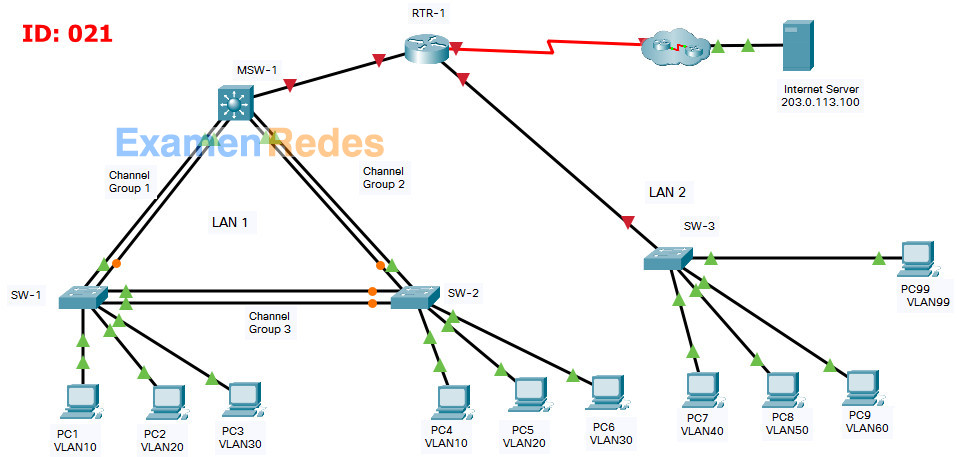
In this assessment you are configuring a network that is using EtherChannel and routing between VLANs. For the sake of time, you will not be asked to perform all configurations on all network devices as you may be required to do in a real network or other assessment. Instead, you will use the skills and knowledge that you have learned in the labs in this course to configure the router and switches in the topology. In addition to EtherChannel and inter-VLAN routing, this task involves creating VLANs and trunks, and performing basic router and switch configuration.
You are required to configure host default gateways; however host addresses are preconfigured.
You will practice and be assessed on the following skills:
- Configuration of initial settings on a router.
- Configuration of initial settings on a switch, including SVI and SSH.
- Configuration of VLANs.
- Configuration of switchport VLAN membership.
- EtherChannel configuration.
- Troubleshooting VLANs.
- Configuration of static trunking and DTP.
- Configuration of routing between VLANs on a Layer 3 switch.
- Configuration of router-on-a-stick inter- VLAN routing on a router.
- Configure default gateways on hosts.
Addressing Table
| Device | Interface | IP Address | Subnet Mask |
|---|---|---|---|
| RTR-1 | G0/0/0 | 172.31.0.1 | 255.255.255. 0 |
| G0/0/1.40 | 172.31.40.1 | 255.255.255.0 | |
| G0/0/1.50 | 172.31.50.1 | 255.255.255.0 | |
| G0/0/1.60 | 172.31.60.1 | 255.255.255.0 | |
| G0/0/1.99 | 172.31.99.17 | 255.255.255.240 | |
| S0/1/0 | 209.165.201.2 | 255.255.255.252 | |
| MSW-1 | G1/1/1 | 172.31.0.2 | 255.255.255.0 |
| VLAN10 | 172.31.10.1 | 255.255.255.0 | |
| VLAN20 | 172.31.20.1 | 255.255.255.0 | |
| VLAN30 | 172.31.30.1 | 255.255.255.0 | |
| VLAN99 | 172.31.99.2 | 255..255.255.240 | |
| SW-3 | VLAN99 | 172.31.99.18 | 255.255.255.240 |
| PC1 | NIC | 172.31.10.10 | 255.255.255.0 |
| PC2 | NIC | 172.31.20.20 | 255.255.255.0 |
| PC3 | NIC | 172.31.30.30 | 255.255.255.0 |
| PC4 | NIC | 172.31.10.11 | 255.255.255.0 |
| PC5 | NIC | 172.31.20.21 | 255.255.255.0 |
| PC6 | NIC | 172.31.30.31 | 255.255.255.0 |
| PC7 | NIC | 172.31.40.40 | 255.255.255.0 |
| PC8 | NIC | 172.31.50.50 | 255.255.255.0 |
| PC9 | NIC | 172.31.60.60 | 255.255.255.0 |
| PC99 | NIC | 172.31.99.19 | 255.255.255.0 |
| Internet Server | NIC | 203.0.113.100 | 255.255.255.0 |
Background / Scenario
A corporation is planning to implement EtherChannel and a new VLAN design in order to make the network more efficient. You have been asked to work on a design and prototype of the new network. You have created the logical topology and now need to configure the devices in order to evaluate the design. You will configure VLANs and access port VLAN membership on access layer switches. You will also configure EtherChannel and trunking. Finally, you will configure a router and a Layer 3 switch to route between VLANs. Some addressing had already been configured.
Instructions
Part 1: Basic Router Configuration
Step 1: Configure router RTR-1 with required settings.
a. Open a command window on router RTR-1 and move to privileged EXEC mode.
b. Copy and paste the following configuration into the RTR-1 router CLI.
ip route 172.31.10.0 255.255.255.0 GigabitEthernet0/0/0

ip route 172.31.20.0 255.255.255.0 GigabitEthernet0/0/0

ip route 172.31.30.0 255.255.255.0 GigabitEthernet0/0/0

ip route 172.31.99.0 255.255.255.240 GigabitEthernet0/0/0
Be sure to press the <Enter> key after the last line to return to privileged EXEC mode prompt.
c. Configure the following settings on the router:
- The enable secret password.
- A console password
- Remote access to the VTY lines.
- A banner MOTD message.
- The device hostname according to the value in the addressing table.
- All clear text passwords should be encrypted.
- Interface addressing on G0/0/0 and S0/1/0.
- Interface descriptions on G0/0/0 and S0/1/0.
Router(config)#no ip domain lookup
Router(config)#enable secret class

Router(config)#line console 0
Router(config-line)#password cisco
Router(config-line)#login
Router(config-line)#exit

Router(config)#line vty 0 4
Router(config-line)#password cisco
Router(config-line)#login
Router(config-line)#exit

Router(config)#banner motd #Authorized Access Only!#

Router(config)#hostname RTR-1

RTR-1(config)#service password-encryption

RTR-1(config)#interface g0/0/0
RTR-1(config-if)#ip address 172.31.0.1 255.255.255.0
RTR-1(config-if)#no shutdown
RTR-1(config-if)#description Link to LAN 1
RTR-1(config-if)#exit

RTR-1(config)#interface s0/1/0
RTR-1(config-if)#ip address 209.165.201.2 255.255.255.252
RTR-1(config-if)#no shutdown
RTR-1(config-if)#description Link to Internet
RTR-1(config-if)#exit
Note: Be sure to make a record of the passwords that you create.
Part 2: Basic Switch Configuration
Step 1: Configure Remote Management Addressing
a. Configure SVI 99 on switch SW-3 with IP addressing according to the Addressing Table.
b. The SW-3 switch SVI should be reachable from other networks.
SW-3(config)#interface vlan 99
SW-3(config-if)#ip address 172.31.99.18 255.255.255.240
SW-3(config-if)#no shutdown
SW-3(config-if)#exit
SW-3(config)#
SW-3(config)#ip default-gateway 172.31.99.17
Step 2: Configure Secure Remote Access
On switch SW-3, configure SSH as follows:
- Username: admin password: C1sco123!
- Modulus bits 1024
- All VTY lines should accept SSH connections only
- Connections should require the previously configured username and password.
- IP domain name: acad.pt
SW-3(config)#ip domain-name acad.pt
SW-3(config)#crypto key generate rsa
How many bits in the modulus [512]: 1024

SW-3(config)#username admin privilege 15 secret C1sco123!
SW-3(config)#enable secret C1sco123!
SW-3(config)#line vty 0 15
SW-3(config-line)#transport input ssh
SW-3(config-line)#login local
SW-3(config-line)#exit
SW-3(config)#ip ssh version 2
Part 3: VLAN Configuration
Step 1: Configure VLANs according to the VLAN table.
Use the VLAN Table to create and name the VLANs on the appropriate switches.
VLAN Table
| VLAN | Name | IP Network | Subnet Mask | Devices |
|---|---|---|---|---|
| 10 | B1F1 | 172.31.10.0 | 255.255.255.0 | MSW-1, SW-1, |
| SW-2 | ||||
| 20 | B1F2 | 172.31.20.0 | 255.255.255.0 | MSW-1, SW-1, |
| SW-2 | ||||
| 30 | B1F4 | 172.31.30.0 | 255.255.255.0 | MSW-1, SW-1, |
| SW-2 | ||||
| 40 | B3 | 172.31.40.0 | 255.255.255.0 | SW-3 |
| 50 | B4 | 172.31.50.0 | 255.255.255.0 | SW-3 |
| 60 | B5 | 172.31.60.0 | 255.255.255.0 | SW-3 |
| 99 | NetAdmin | 172.31.99.16 | 255.255.255.240 | SW-3, MSW-1 |
MSW-1
MSW-1(config)#vlan 10
MSW-1(config-vlan)#name B1F1
MSW-1(config-vlan)#interface vlan 10
MSW-1(config-if)#description B1F1
MSW-1(config-if)#ip address 172.31.10.1 255.255.255.0
MSW-1(config-if)#exit
MSW-1(config)#
MSW-1(config)#vlan 20
MSW-1(config-vlan)#name B1F2
MSW-1(config-vlan)#interface vlan 20
MSW-1(config-if)#description B1F2
MSW-1(config-if)#ip address 172.31.20.1 255.255.255.0
MSW-1(config-if)#exit
MSW-1(config)#
MSW-1(config)#vlan 30
MSW-1(config-vlan)#name B1F4
MSW-1(config-vlan)#interface vlan 30
MSW-1(config-if)#description B1F4
MSW-1(config-if)#ip address 172.31.30.1 255.255.255.0
MSW-1(config-if)#exit
MSW-1(config)#
MSW-1(config)#vlan 99
MSW-1(config-vlan)#name NetAdmin
MSW-1(config-vlan)#interface vlan 99
MSW-1(config-if)#description NetAdmin
MSW-1(config-if)#ip address 172.31.99.2 255.255.255.240
MSW-1(config-if)#exit
SW-1
SW-1(config)#vlan 10
SW-1(config-vlan)#name B1F1
SW-1(config-vlan)#interface vlan 10
SW-1(config-if)#description B1F1
SW-1(config-if)#exit
SW-1(config)#
SW-1(config)#vlan 20
SW-1(config-vlan)#name B1F2
SW-1(config-vlan)#interface vlan 20
SW-1(config-if)#description B1F2
SW-1(config-if)#exit
SW-1(config)#
SW-1(config)#vlan 30
SW-1(config-vlan)#name B1F4
SW-1(config-vlan)#interface vlan 30
SW-1(config-if)#description B1F4
SW-1(config-if)#exit
SW-2
SW-2(config)#vlan 10
SW-2(config-vlan)#name B1F1
SW-2(config-vlan)#interface vlan 10
SW-2(config-if)#description B1F1
SW-2(config-if)#exit
SW-2(config)#
SW-2(config)#vlan 20
SW-2(config-vlan)#name B1F2
SW-2(config-vlan)#interface vlan 20
SW-2(config-if)#description B1F2
SW-2(config-if)#exit
SW-2(config)#
SW-2(config)#vlan 30
SW-2(config-vlan)#name B1F4
SW-2(config-vlan)#interface vlan 30
SW-2(config-if)#description B1F4
SW-2(config-if)#exit
SW-3
SW-3(config)#vlan 40
SW-3(config-vlan)#name B3
SW-3(config-vlan)#interface vlan 40
SW-3(config-if)#ip address 172.31.40.1 255.255.255.0
SW-3(config-if)#description B3
SW-3(config-if)#exit
SW-3(config)#
SW-3(config)#vlan 50
SW-3(config-vlan)#name B4
SW-3(config-vlan)#interface vlan 50
SW-3(config-if)#ip address 172.31.50.1 255.255.255.0
SW-3(config-if)#description B4
SW-3(config-if)#exit
SW-3(config)#
SW-3(config)#vlan 60
SW-3(config-vlan)#name B5
SW-3(config-vlan)#interface vlan 60
SW-3(config-if)#ip address 172.31.60.1 255.255.255.0
SW-3(config-if)#description B5
SW-3(config-if)#exit
SW-3(config)#
SW-3(config)#vlan 99
SW-3(config-vlan)#name NetAdmin
SW-3(config-vlan)#interface vlan 99
SW-3(config-if)#ip address 172.31.99.18 255.255.255.240
SW-3(config-if)#description NetAdmin
SW-3(config-if)#exit
Step 2: Assign switch ports to VLANs.
Assign VLAN membership to static access switchports according to the Port to VLAN Assignment table.
Port to VLAN Assignment Table
| Device | VLAN | VLAN Name | Port Assignments |
|---|---|---|---|
| SW-1 | 10 | B1F1 | F0/7-10 |
| 20 | B1F2 | F0/11-15 | |
| 30 | B1F4 | F0/16-24 | |
| SW-2 | 10 | B1F1 | F0/7-10 |
| 20 | B1F2 | F0/11-15 | |
| 30 | B1F4 | F0/16-24 | |
| SW-3 | 40 | FAC | F0/1-5 |
| 50 | B4 | F0/6-10 | |
| 60 | B5 | F0/11-15 | |
| 99 | ADMIN Native | F0/24 |
SW-1
SW-1(config)#interface range f0/7-10
SW-1(config-if-range)#switchport mode access
SW-1(config-if-range)#switchport access vlan 10
SW-1(config-if-range)#exit
SW-1(config)#interface range f0/11-15
SW-1(config-if-range)#switchport mode access
SW-1(config-if-range)#switchport access vlan 20
SW-1(config-if-range)#exit
SW-1(config)#interface range f0/16-24
SW-1(config-if-range)#switchport mode access
SW-1(config-if-range)#switchport access vlan 30
SW-1(config-if-range)#exit
SW-2
SW-2(config)#interface range f0/7-10
SW-2(config-if-range)#switchport mode access
SW-2(config-if-range)#switchport access vlan 10
SW-2(config-if-range)#exit
SW-2(config)#interface range f0/11-15
SW-2(config-if-range)#switchport mode access
SW-2(config-if-range)#switchport access vlan 20
SW-2(config-if-range)#exit
SW-2(config)#interface range f0/16-24
SW-2(config-if-range)#switchport mode access
SW-2(config-if-range)#switchport access vlan 30
SW-2(config-if-range)#exit
SW-3
SW-3(config)#interface range f0/1-5
SW-3(config-if-range)#switchport mode access
SW-3(config-if-range)#switchport access vlan 40
SW-3(config-if-range)#exit
SW-3(config)#interface range f0/6-10
SW-3(config-if-range)#switchport mode access
SW-3(config-if-range)#switchport access vlan 50
SW-3(config-if-range)#exit
SW-3(config)#interface range f0/11-15
SW-3(config-if-range)#switchport mode access
SW-3(config-if-range)#switchport access vlan 60
SW-3(config-if-range)#exit
SW-3(config)#interface f0/24
SW-3(config-if)#switchport mode access
SW-3(config-if)#switchport access vlan 99
SW-3(config-if)#exit
Part 4: EtherChannel and Trunking Configuration
EtherChannel Port Assignments Table
| Channel Group | Devices in Groups | Ports in Group |
|---|---|---|
| 1 | MSW-1 | G1/0/1, G1/0/2 |
| SW-1 | G0/1, G0/2 | |
| 2 | MSW-1 | G1/0/3, G1/0/4 |
| SW-2 | G0/1, G0/2 | |
| 3 | SW-1 | F0/5, F0/6 |
| SW-2 | F0/5, F0/6 |
Step 1: Configure EtherChannels
Create EtherChannels according to the EtherChannel Port Assignments Table. Use the Cisco LACP protocol. Both sides of the channel should attempt to negotiate the link protocol.
MSW-1
MSW-1(config)#interface range g1/0/1-2
MSW-1(config-if-range)#channel-group 1 mode active
MSW-1(config-if-range)#exit
MSW-1(config)#
MSW-1(config)#interface range g1/0/3-4
MSW-1(config-if-range)#channel-group 2 mode active
MSW-1(config-if-range)#exit
SW-1
SW-1(config)#interface range g0/1-2
SW-1(config-if-range)#channel-group 1 mode active
SW-1(config-if-range)#exit
SW-1(config)#
SW-1(config)#interface range f0/5-6
SW-1(config-if-range)#channel-group 3 mode active
SW-1(config-if-range)#exit
SW-2
SW-2(config)#interface range g0/1-2
SW-2(config-if-range)#channel-group 2 mode active
SW-2(config-if-range)#exit
SW-2(config)#
SW-2(config)#interface range f0/5-6
SW-2(config-if-range)#channel-group 3 mode active
SW-2(config-if-range)#exit
Step 2: Configure Trunking on the EtherChannels
a. Configure the port channel interfaces as static trunks. Disable DTP negotiation on all trunks.
b. Troubleshoot any issues that prevent the formation of the EtherChannels.
MSW-1
MSW-1(config)#interface port-channel 1
MSW-1(config-if)#switchport mode trunk
MSW-1(config-if)#switchport trunk allowed vlan 10,20,30
MSW-1(config-if)#exit
MSW-1(config)#
MSW-1(config)#interface port-channel 2
MSW-1(config-if)#switchport mode trunk
MSW-1(config-if)#switchport trunk allowed vlan 10,20,30
MSW-1(config-if)#exit
SW-1
SW-1(config)#interface port-channel 1
SW-1(config-if)#switchport mode trunk
SW-1(config-if)#switchport nonegotiate
SW-1(config-if)#exit
SW-1(config)#
SW-1(config)#interface port-channel 3
SW-1(config-if)#switchport mode trunk

SW-1(config-if)#switchport nonegotiate
SW-1(config-if)#exit
SW-2
SW-2(config)#interface port-channel 2
SW-2(config-if)#switchport mode trunk
SW-2(config-if)#switchport nonegotiate
SW-2(config-if)#exit
SW-2(config)#
SW-2(config)#interface port-channel 3
SW-2(config-if)#switchport mode trunk

SW-2(config-if)#switchport nonegotiate
SW-2(config-if)#exit
Note: Packet Tracer requires configuration of trunking and DTP mode on both portchannel interfaces and the component physical interfaces.
Step 3: Configure a static trunk uplink
a. On the SW-3 switch, configure the port that is connected to RTR-1 G0/0/0 as a static trunk.
b. Configure the NetAdmin VLAN as the native VLAN.
c. Disable DTP on the port.
SW-3
SW-3(config)#interface g0/1
SW-3(config-if)#switchport mode trunk
SW-3(config-if)#switchport nonegotiate
SW-3(config-if)#switchport trunk native vlan 99
SW-3(config-if)#switchport trunk allowed vlan 40,50,60,99
SW-3(config-if)#exit
Part 5: Configure Inter-VLAN Routing
Step 1: Configure inter-VLAN routing on the Layer 3 switch.
a. Configure Inter-VLAN routing on the MSW-1 Layer 3 switch for all VLANs in the VLAN Table that are configured on MSW-1.
b. Configure the switchport on MSW-1 that is connected to RTR-1 with an IP address as shown in the Addressing Table.
MSW-1
MSW-1(config)#ip routing
MSW-1(config)#interface g1/1/1
MSW-1(config-if)#no switchport
MSW-1(config-if)#ip address 172.31.0.2 255.255.255.0
Step 2: Configure router-on-a-stick inter-VLAN routing on a router.
a. Configure inter-VLAN routing on RTR-1 for all the VLANs that are configured on the SW-3 switch. Use the information in the Addressing Table.
b. Be sure to configure descriptions of all interfaces.
RTR-1
RTR-1(config)#interface g0/0/1
RTR-1(config-if)#no shutdown
RTR-1(config)#interface g0/0/1.40
RTR-1(config-subif)#description "Gateway for VLAN40"
RTR-1(config-subif)#encapsulation dot1q 40
RTR-1(config-subif)#ip address 172.31.40.1 255.255.255.0
RTR-1(config-subif)#exit
RTR-1(config)#interface g0/0/1.50
RTR-1(config-subif)#description "Gateway for VLAN50"
RTR-1(config-subif)#encapsulation dot1q 50
RTR-1(config-subif)#ip address 172.31.50.1 255.255.255.0
RTR-1(config-subif)#exit
RTR-1(config)#interface g0/0/1.60
RTR-1(config-subif)#description "Gateway for VLAN60"
RTR-1(config-subif)#encapsulation dot1q 60
RTR-1(config-subif)#ip address 172.31.60.1 255.255.255.0
RTR-1(config-subif)#exit
RTR-1(config)#interface g0/0/1.99
RTR-1(config-subif)#description "Gateway for VLAN99"
RTR-1(config-subif)#encapsulation dot1q 99 native
RTR-1(config-subif)#ip address 172.31.99.17 255.255.255.240
RTR-1(config-subif)#exit
Step 3: Configure default gateways on hosts.
a. Configure default gateway addresses on all hosts on the LANs.
Default gateway on PC2 and PC5: 172.31.20.1
Default gateway on PC3 and PC6: 172.31.30.1
Default gateway on PC7: 172.31.40.1
Default gateway on PC8: 172.31.50.1
Default gateway on PC9: 172.31.60.1
Default gateway on PC99: 172.31.99.17
c. Verify that a host can connect to the SVI of switch SW-3 over SSH.
Last Updated: January 2021
ID 021
Intructions – Answers
Router RTR-1
en
conf t
ip route 172.31.10.0 255.255.255.0 GigabitEthernet0/0/0
ip route 172.31.20.0 255.255.255.0 GigabitEthernet0/0/0
ip route 172.31.30.0 255.255.255.0 GigabitEthernet0/0/0
ip route 172.31.99.0 255.255.255.240 GigabitEthernet0/0/0
no ip domain lookup

enable secret class
line console 0
password cisco
login
exit
line vty 0 4
password cisco
login
exit
banner motd #Authorized Access Only!#
hostname RTR-1
service password-encryption
interface g0/0/0
ip address 172.31.0.1 255.255.255.0
no shutdown
description "R1 G0/0/0"
exit
interface s0/1/0
ip address 209.165.201.2 255.255.255.252
no shutdown
description "R1 S0/1/0"
exit

interface g0/0/1
no shutdown

interface g0/0/1.40
description "Gateway for VLAN40"
encapsulation dot1q 40
ip address 172.31.40.1 255.255.255.0
exit
interface g0/0/1.50
description "Gateway for VLAN50"
encapsulation dot1q 50
ip address 172.31.50.1 255.255.255.0
exit
interface g0/0/1.60
description "Gateway for VLAN60"
encapsulation dot1q 60
ip address 172.31.60.1 255.255.255.0
exit
interface g0/0/1.99
description "Gateway for VLAN99"
encapsulation dot1q 99 native
ip address 172.31.99.17 255.255.255.240
end
copy running-config startup-config
Switch SW-3
en
config t
interface vlan 99
ip address 172.31.99.18 255.255.255.240
no shutdown
exit
ip default-gateway 172.31.99.17
ip domain-name acad.pt
crypto key generate rsa
1024

username admin privilege 15 secret C1sco123!
enable secret C1sco123!
line vty 0 15
transport input ssh
login local
exit
ip ssh version 2

vlan 40
name B3
exit
interface vlan 40
ip address 172.31.40.1 255.255.255.0
description B3
exit
vlan 50
name B4
exit
interface vlan 50
ip address 172.31.50.1 255.255.255.0
description B4
exit
vlan 60
name B5
exit
interface vlan 60
ip address 172.31.60.1 255.255.255.0
description B5
exit
vlan 99
name NetAdmin
exit
interface vlan 99
ip address 172.31.99.18 255.255.255.240
description NetAdmin
exit

interface range f0/1-5
switchport mode access
switchport access vlan 40
exit
interface range f0/6-10
switchport mode access
switchport access vlan 50
exit
interface range f0/11-15
switchport mode access
switchport access vlan 60
exit
interface f0/24
switchport mode access
switchport access vlan 99
exit
interface g0/1
switchport mode trunk
switchport nonegotiate
switchport trunk allowed vlan 40,50,60,99
switchport trunk native vlan 99
end
copy running-config startup-config
Switch MSW-1
en
config t
vlan 10
name B1F1
interface vlan 10
description B1F1
ip address 172.31.10.1 255.255.255.0
exit
vlan 20
name B1F2
interface vlan 20
description B1F2
ip address 172.31.20.1 255.255.255.0
exit
vlan 30
name B1F4
interface vlan 30
description B1F4
ip address 172.31.30.1 255.255.255.0
exit
vlan 99
name NetAdmin
interface vlan 99
description NetAdmin
ip address 172.31.99.2 255.255.255.240
exit

ip routing
interface g1/1/1
no switchport
ip address 172.31.0.2 255.255.255.0
exit

interface range g1/0/1-2
channel-group 1 mode active
exit
interface port-channel 1
switchport mode trunk
switchport trunk allowed vlan 10,20,30
exit
interface range g1/0/3-4
channel-group 2 mode active
exit
interface port-channel 2
switchport mode trunk
switchport trunk allowed vlan 10,20,30
end
copy running-config startup-config
Switch SW-1
enable
config terminal
vlan 10
name B1F1
interface vlan 10
description B1F1
exit
vlan 20
name B1F2
interface vlan 20
description B1F2
exit
vlan 30
name B1F4
interface vlan 30
description B1F4
exit

interface range f0/7-10
switchport mode access
switchport access vlan 10
exit
interface range f0/11-15
switchport mode access
switchport access vlan 20
exit
interface range f0/16-24
switchport mode access
switchport access vlan 30
exit

interface range g0/1-2
channel-group 1 mode active
exit
interface port-channel 1
switchport mode trunk
switchport nonegotiate
exit
interface range f0/5-6
channel-group 3 mode active
exit
interface port-channel 3
switchport mode trunk
switchport nonegotiate
end
copy running-config startup-config
Switch SW-2
en
config t
vlan 10
name B1F1
interface vlan 10
description B1F1
exit
vlan 20
name B1F2
interface vlan 20
description B1F2
exit
vlan 30
name B1F4
interface vlan 30
description B1F4
exit

interface range f0/7-10
switchport mode access
switchport access vlan 10
exit
interface range f0/11-15
switchport mode access
switchport access vlan 20
exit
interface range f0/16-24
switchport mode access
switchport access vlan 30
exit

interface range g0/1-2
channel-group 2 mode active
exit
interface port-channel 2
switchport mode trunk
switchport nonegotiate
exit
interface range f0/5-6
channel-group 3 mode active
exit
interface port-channel 3
switchport mode trunk
switchport nonegotiate
end
copy running-config startup-config
Configure default gateway addresses on all hosts on the LANs.
Default gateway on PC2 and PC5: 172.31.20.1
Default gateway on PC3 and PC6: 172.31.30.1
Default gateway on PC7: 172.31.40.1
Default gateway on PC8: 172.31.50.1
Default gateway on PC9: 172.31.60.1
Default gateway on PC99: 172.31.99.17
CCNAv7 Switching, Routing, and Wireless Essentials v7.0 (SRWE) Answers
SRWE PT Practice Skills Assessment (PTSA) Part 1
A few things to keep in mind while completing this activity:
- Do not use the browser Back button or close or reload any exam windows during the exam.
- Do not close Packet Tracer when you are done. It will close automatically.
- Click the Submit Assessment button in the browser window to submit your work.
Introduction
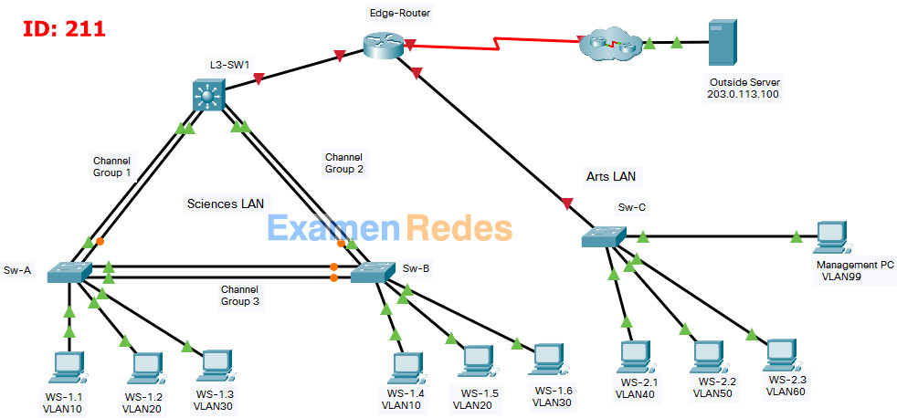
In this assessment you are configuring a network that is using EtherChannel and routing between VLANs. For the sake of time, you will not be asked to perform all configurations on all network devices as you may be required to do in a real network or other assessment. Instead, you will use the skills and knowledge that you have learned in the labs in this course to configure the router and switches in the topology. In addition to EtherChannel and inter-VLAN routing, this task involves creating VLANs and trunks, and performing basic router and switch configuration.
You are required to configure host default gateways; however host addresses are preconfigured.
You will practice and be assessed on the following skills:
- Configuration of initial settings on a router.
- Configuration of initial settings on a switch, including SVI and SSH.
- Configuration of VLANs.
- Configuration of switchport VLAN membership.
- EtherChannel configuration.
- Troubleshooting VLANs.
- Configuration of static trunking and DTP.
- Configuration of routing between VLANs on a Layer 3 switch.
- Configuration of router-on-a-stick inter- VLAN routing on a router.
- Configure default gateways on hosts.
Addressing Table
| Device | Interface | IP Address | Subnet Mask |
|---|---|---|---|
| Edge-Router | G0/0/0 | 172.31.0.1 | 255.255.255. 0 |
| G0/0/1.40 | 172.31.40.1 | 255.255.255.0 | |
| G0/0/1.50 | 172.31.50.1 | 255.255.255.0 | |
| G0/0/1.60 | 172.31.60.1 | 255.255.255.0 | |
| G0/0/1.99 | 172.31.99.17 | 255.255.255.240 | |
| S0/1/0 | 209.165.201.2 | 255.255.255.252 | |
| L3-SW1 | G1/1/1 | 172.31.0.2 | 255.255.255.0 |
| VLAN10 | 172.31.10.1 | 255.255.255.0 | |
| VLAN20 | 172.31.20.1 | 255.255.255.0 | |
| VLAN30 | 172.31.30.1 | 255.255.255.0 | |
| VLAN99 | 172.31.99.2 | 255..255.255.240 | |
| Sw-C | VLAN99 | 172.31.99.18 | 255.255.255.240 |
| WS-1.1 | NIC | 172.31.10.10 | 255.255.255.0 |
| WS-1.2 | NIC | 172.31.20.20 | 255.255.255.0 |
| WS-1.3 | NIC | 172.31.30.30 | 255.255.255.0 |
| WS-1.4 | NIC | 172.31.10.11 | 255.255.255.0 |
| WS-1.5 | NIC | 172.31.20.21 | 255.255.255.0 |
| WS-1.6 | NIC | 172.31.30.31 | 255.255.255.0 |
| WS-2.1 | NIC | 172.31.40.40 | 255.255.255.0 |
| WS-2.2 | NIC | 172.31.50.50 | 255.255.255.0 |
| WS-2.3 | NIC | 172.31.60.60 | 255.255.255.0 |
| Management PC | NIC | 172.31.99.19 | 255.255.255.0 |
| Outside Server | NIC | 203.0.113.100 | 255.255.255.0 |
Background / Scenario
A corporation is planning to implement EtherChannel and a new VLAN design in order to make the network more efficient. You have been asked to work on a design and prototype of the new network. You have created the logical topology and now need to configure the devices in order to evaluate the design. You will configure VLANs and access port VLAN membership on access layer switches. You will also configure EtherChannel and trunking. Finally, you will configure a router and a Layer 3 switch to route between VLANs. Some addressing had already been configured.
Instructions
Part 1: Basic Router Configuration
Step 1: Configure router Edge-Router with required settings.
a. Open a command window on router Edge-Router and move to privileged EXEC mode.
b. Copy and paste the following configuration into the Edge-Router router CLI.
ip route 172.31.10.0 255.255.255.0 GigabitEthernet0/0/0

ip route 172.31.20.0 255.255.255.0 GigabitEthernet0/0/0

ip route 172.31.30.0 255.255.255.0 GigabitEthernet0/0/0

ip route 172.31.99.0 255.255.255.240 GigabitEthernet0/0/0
Be sure to press the <Enter> key after the last line to return to privileged EXEC mode prompt.
c. Configure the following settings on the router:
- The enable secret password.
- A console password
- Remote access to the VTY lines.
- A banner MOTD message.
- The device hostname according to the value in the addressing table.
- All clear text passwords should be encrypted.
- Interface addressing on G0/0/0 and S0/1/0.
- Interface descriptions on G0/0/0 and S0/1/0.
Router(config)#no ip domain lookup
Router(config)#enable secret class

Router(config)#line console 0
Router(config-line)#password cisco
Router(config-line)#login
Router(config-line)#exit

Router(config)#line vty 0 4
Router(config-line)#password cisco
Router(config-line)#login
Router(config-line)#exit

Router(config)#banner motd #Authorized Access Only!#

Router(config)#hostname Edge-Router

Edge-Router(config)#service password-encryption

Edge-Router(config)#interface g0/0/0
Edge-Router(config-if)#ip address 172.31.0.1 255.255.255.0
Edge-Router(config-if)#no shutdown
Edge-Router(config-if)#description Link to LAN 1
Edge-Router(config-if)#exit

Edge-Router(config)#interface s0/1/0
Edge-Router(config-if)#ip address 209.165.201.2 255.255.255.252
Edge-Router(config-if)#no shutdown
Edge-Router(config-if)#description Link to Internet
Edge-Router(config-if)#exit
Note: Be sure to make a record of the passwords that you create.
Part 2: Basic Switch Configuration
Step 1: Configure Remote Management Addressing
a. Configure SVI 99 on switch Sw-C with IP addressing according to the Addressing Table.
b. The Sw-C switch SVI should be reachable from other networks.
Sw-C(config)#interface vlan 99
Sw-C(config-if)#ip address 172.31.99.18 255.255.255.240
Sw-C(config-if)#no shutdown
Sw-C(config-if)#exit
Sw-C(config)#
Sw-C(config)#ip default-gateway 172.31.99.17
Step 2: Configure Secure Remote Access
On switch Sw-C, configure SSH as follows:
- Username: admin password: C1sco123!
- Modulus bits 1024
- All VTY lines should accept SSH connections only
- Connections should require the previously configured username and password.
- IP domain name: acad.pt
Sw-C(config)#ip domain-name acad.pt
Sw-C(config)#crypto key generate rsa
How many bits in the modulus [512]: 1024

Sw-C(config)#username admin privilege 15 secret C1sco123!
Sw-C(config)#enable secret C1sco123!
Sw-C(config)#line vty 0 15
Sw-C(config-line)#transport input ssh
Sw-C(config-line)#login local
Sw-C(config-line)#exit
Sw-C(config)#ip ssh version 2
Part 3: VLAN Configuration
Step 1: Configure VLANs according to the VLAN table.
Use the VLAN Table to create and name the VLANs on the appropriate switches.
VLAN Table
| VLAN | Name | IP Network | Subnet Mask | Devices |
|---|---|---|---|---|
| 10 | SALES | 172.31.10.0 | 255.255.255.0 | L3-SW1, Sw-A, |
| Sw-B | ||||
| 20 | ACCT | 172.31.20.0 | 255.255.255.0 | L3-SW1, Sw-A, |
| Sw-B | ||||
| 30 | EXEC | 172.31.30.0 | 255.255.255.0 | L3-SW1, Sw-A, |
| Sw-B | ||||
| 40 | FAC | 172.31.40.0 | 255.255.255.0 | Sw-C |
| 50 | FAB1 | 172.31.50.0 | 255.255.255.0 | Sw-C |
| 60 | FAB2 | 172.31.60.0 | 255.255.255.0 | Sw-C |
| 99 | ADMIN | 172.31.99.16 | 255.255.255.240 | Sw-C, L3-SW1 |
L3-SW1
L3-SW1(config)#vlan 10
L3-SW1(config-vlan)#name SALES
L3-SW1(config-vlan)#interface vlan 10
L3-SW1(config-if)#description SALES
L3-SW1(config-if)#ip address 172.31.10.1 255.255.255.0
L3-SW1(config-if)#exit
L3-SW1(config)#
L3-SW1(config)#vlan 20
L3-SW1(config-vlan)#name ACCT
L3-SW1(config-vlan)#interface vlan 20
L3-SW1(config-if)#description ACCT
L3-SW1(config-if)#ip address 172.31.20.1 255.255.255.0
L3-SW1(config-if)#exit
L3-SW1(config)#
L3-SW1(config)#vlan 30
L3-SW1(config-vlan)#name EXEC
L3-SW1(config-vlan)#interface vlan 30
L3-SW1(config-if)#description EXEC
L3-SW1(config-if)#ip address 172.31.30.1 255.255.255.0
L3-SW1(config-if)#exit
L3-SW1(config)#
L3-SW1(config)#vlan 99
L3-SW1(config-vlan)#name ADMIN
L3-SW1(config-vlan)#interface vlan 99
L3-SW1(config-if)#description ADMIN
L3-SW1(config-if)#ip address 172.31.99.2 255.255.255.240
L3-SW1(config-if)#exit
Sw-A
Sw-A(config)#vlan 10
Sw-A(config-vlan)#name SALES
Sw-A(config-vlan)#interface vlan 10
Sw-A(config-if)#description SALES
Sw-A(config-if)#exit
Sw-A(config)#
Sw-A(config)#vlan 20
Sw-A(config-vlan)#name ACCT
Sw-A(config-vlan)#interface vlan 20
Sw-A(config-if)#description ACCT
Sw-A(config-if)#exit
Sw-A(config)#
Sw-A(config)#vlan 30
Sw-A(config-vlan)#name EXEC
Sw-A(config-vlan)#interface vlan 30
Sw-A(config-if)#description EXEC
Sw-A(config-if)#exit
Sw-B
Sw-B(config)#vlan 10
Sw-B(config-vlan)#name SALES
Sw-B(config-vlan)#interface vlan 10
Sw-B(config-if)#description SALES
Sw-B(config-if)#exit
Sw-B(config)#
Sw-B(config)#vlan 20
Sw-B(config-vlan)#name ACCT
Sw-B(config-vlan)#interface vlan 20
Sw-B(config-if)#description ACCT
Sw-B(config-if)#exit
Sw-B(config)#
Sw-B(config)#vlan 30
Sw-B(config-vlan)#name EXEC
Sw-B(config-vlan)#interface vlan 30
Sw-B(config-if)#description EXEC
Sw-B(config-if)#exit
Sw-C
Sw-C(config)#vlan 40
Sw-C(config-vlan)#name FAC
Sw-C(config-vlan)#interface vlan 40
Sw-C(config-if)#ip address 172.31.40.1 255.255.255.0
Sw-C(config-if)#description FAC
Sw-C(config-if)#exit
Sw-C(config)#
Sw-C(config)#vlan 50
Sw-C(config-vlan)#name FAB1
Sw-C(config-vlan)#interface vlan 50
Sw-C(config-if)#ip address 172.31.50.1 255.255.255.0
Sw-C(config-if)#description FAB1
Sw-C(config-if)#exit
Sw-C(config)#
Sw-C(config)#vlan 60
Sw-C(config-vlan)#name FAB2
Sw-C(config-vlan)#interface vlan 60
Sw-C(config-if)#ip address 172.31.60.1 255.255.255.0
Sw-C(config-if)#description FAB2
Sw-C(config-if)#exit
Sw-C(config)#
Sw-C(config)#vlan 99
Sw-C(config-vlan)#name ADMIN
Sw-C(config-vlan)#interface vlan 99
Sw-C(config-if)#ip address 172.31.99.18 255.255.255.240
Sw-C(config-if)#description ADMIN
Sw-C(config-if)#exit
Step 2: Assign switch ports to VLANs.
Assign VLAN membership to static access switchports according to the Port to VLAN Assignment table.
Port to VLAN Assignment Table
| Device | VLAN | VLAN Name | Port Assignments |
|---|---|---|---|
| Sw-A | 10 | SALES | F0/7-10 |
| 20 | ACCT | F0/11-15 | |
| 30 | EXEC | F0/16-24 | |
| Sw-B | 10 | SALES | F0/7-10 |
| 20 | ACCT | F0/11-15 | |
| 30 | EXEC | F0/16-24 | |
| Sw-C | 40 | FAC | F0/1-5 |
| 50 | FAB1 | F0/6-10 | |
| 60 | FAB2 | F0/11-15 | |
| 99 | ADMIN Native | F0/24 |
Sw-A
Sw-A(config)#interface range f0/7-10
Sw-A(config-if-range)#switchport mode access
Sw-A(config-if-range)#switchport access vlan 10
Sw-A(config-if-range)#exit
Sw-A(config)#interface range f0/11-15
Sw-A(config-if-range)#switchport mode access
Sw-A(config-if-range)#switchport access vlan 20
Sw-A(config-if-range)#exit
Sw-A(config)#interface range f0/16-24
Sw-A(config-if-range)#switchport mode access
Sw-A(config-if-range)#switchport access vlan 30
Sw-A(config-if-range)#exit
Sw-B
Sw-B(config)#interface range f0/7-10
Sw-B(config-if-range)#switchport mode access
Sw-B(config-if-range)#switchport access vlan 10
Sw-B(config-if-range)#exit
Sw-B(config)#interface range f0/11-15
Sw-B(config-if-range)#switchport mode access
Sw-B(config-if-range)#switchport access vlan 20
Sw-B(config-if-range)#exit
Sw-B(config)#interface range f0/16-24
Sw-B(config-if-range)#switchport mode access
Sw-B(config-if-range)#switchport access vlan 30
Sw-B(config-if-range)#exit
Sw-C
Sw-C(config)#interface range f0/1-5
Sw-C(config-if-range)#switchport mode access
Sw-C(config-if-range)#switchport access vlan 40
Sw-C(config-if-range)#exit
Sw-C(config)#interface range f0/6-10
Sw-C(config-if-range)#switchport mode access
Sw-C(config-if-range)#switchport access vlan 50
Sw-C(config-if-range)#exit
Sw-C(config)#interface range f0/11-15
Sw-C(config-if-range)#switchport mode access
Sw-C(config-if-range)#switchport access vlan 60
Sw-C(config-if-range)#exit
Sw-C(config)#interface f0/24
Sw-C(config-if)#switchport mode access
Sw-C(config-if)#switchport access vlan 99
Sw-C(config-if)#exit
Part 4: EtherChannel and Trunking Configuration
EtherChannel Port Assignments Table
| Channel Group | Devices in Groups | Ports in Group |
|---|---|---|
| 1 | L3-SW1 | G1/0/1, G1/0/2 |
| Sw-A | G0/1, G0/2 | |
| 2 | L3-SW1 | G1/0/3, G1/0/4 |
| Sw-B | G0/1, G0/2 | |
| 3 | Sw-A | F0/5, F0/6 |
| Sw-B | F0/5, F0/6 |
Step 1: Configure EtherChannels
Create EtherChannels according to the EtherChannel Port Assignments Table. Use the Cisco LACP protocol. Both sides of the channel should attempt to negotiate the link protocol.
L3-SW1
L3-SW1(config)#interface range g1/0/1-2
L3-SW1(config-if-range)#channel-group 1 mode active
L3-SW1(config-if-range)#exit
L3-SW1(config)#
L3-SW1(config)#interface range g1/0/3-4
L3-SW1(config-if-range)#channel-group 2 mode active
L3-SW1(config-if-range)#exit
Sw-A
Sw-A(config)#interface range g0/1-2
Sw-A(config-if-range)#channel-group 1 mode active
Sw-A(config-if-range)#exit
Sw-A(config)#
Sw-A(config)#interface range f0/5-6
Sw-A(config-if-range)#channel-group 3 mode active
Sw-A(config-if-range)#exit
Sw-B
Sw-B(config)#interface range g0/1-2
Sw-B(config-if-range)#channel-group 2 mode active
Sw-B(config-if-range)#exit
Sw-B(config)#
Sw-B(config)#interface range f0/5-6
Sw-B(config-if-range)#channel-group 3 mode active
Sw-B(config-if-range)#exit
Step 2: Configure Trunking on the EtherChannels
a. Configure the port channel interfaces as static trunks. Disable DTP negotiation on all trunks.
b. Troubleshoot any issues that prevent the formation of the EtherChannels.
L3-SW1
L3-SW1(config)#interface port-channel 1
L3-SW1(config-if)#switchport mode trunk
L3-SW1(config-if)#switchport trunk allowed vlan 10,20,30
L3-SW1(config-if)#exit
L3-SW1(config)#
L3-SW1(config)#interface port-channel 2
L3-SW1(config-if)#switchport mode trunk
L3-SW1(config-if)#switchport trunk allowed vlan 10,20,30
L3-SW1(config-if)#exit
Sw-A
Sw-A(config)#interface port-channel 1
Sw-A(config-if)#switchport mode trunk
Sw-A(config-if)#switchport nonegotiate
Sw-A(config-if)#exit
Sw-A(config)#
Sw-A(config)#interface port-channel 3
Sw-A(config-if)#switchport mode trunk

Sw-A(config-if)#switchport nonegotiate
Sw-A(config-if)#exit
Sw-B
Sw-B(config)#interface port-channel 2
Sw-B(config-if)#switchport mode trunk
Sw-B(config-if)#switchport nonegotiate
Sw-B(config-if)#exit
Sw-B(config)#
Sw-B(config)#interface port-channel 3
Sw-B(config-if)#switchport mode trunk

Sw-B(config-if)#switchport nonegotiate
Sw-B(config-if)#exit
Note: Packet Tracer requires configuration of trunking and DTP mode on both portchannel interfaces and the component physical interfaces.
Step 3: Configure a static trunk uplink
a. On the Sw-C switch, configure the port that is connected to Edge-Router G0/0/0 as a static trunk.
b. Configure the ADMIN VLAN as the native VLAN.
c. Disable DTP on the port.
Sw-C
Sw-C(config)#interface g0/1
Sw-C(config-if)#switchport mode trunk
Sw-C(config-if)#switchport nonegotiate
Sw-C(config-if)#switchport trunk native vlan 99
Sw-C(config-if)#switchport trunk allowed vlan 40,50,60,99
Sw-C(config-if)#exit
Part 5: Configure Inter-VLAN Routing
Step 1: Configure inter-VLAN routing on the Layer 3 switch.
a. Configure Inter-VLAN routing on the L3-SW1 Layer 3 switch for all VLANs in the VLAN Table that are configured on L3-SW1.
b. Configure the switchport on L3-SW1 that is connected to Edge-Router with an IP address as shown in the Addressing Table.
L3-SW1
L3-SW1(config)#ip routing
L3-SW1(config)#interface g1/1/1
L3-SW1(config-if)#no switchport
L3-SW1(config-if)#ip address 172.31.0.2 255.255.255.0
Step 2: Configure router-on-a-stick inter-VLAN routing on a router.
a. Configure inter-VLAN routing on Edge-Router for all the VLANs that are configured on the Sw-C switch. Use the information in the Addressing Table.
b. Be sure to configure descriptions of all interfaces.
Edge-Router
Edge-Router(config)#interface g0/0/1
Edge-Router(config-if)#no shutdown
Edge-Router(config)#interface g0/0/1.40
Edge-Router(config-subif)#description "Gateway for VLAN40"
Edge-Router(config-subif)#encapsulation dot1q 40
Edge-Router(config-subif)#ip address 172.31.40.1 255.255.255.0
Edge-Router(config-subif)#exit
Edge-Router(config)#interface g0/0/1.50
Edge-Router(config-subif)#description "Gateway for VLAN50"
Edge-Router(config-subif)#encapsulation dot1q 50
Edge-Router(config-subif)#ip address 172.31.50.1 255.255.255.0
Edge-Router(config-subif)#exit
Edge-Router(config)#interface g0/0/1.60
Edge-Router(config-subif)#description "Gateway for VLAN60"
Edge-Router(config-subif)#encapsulation dot1q 60
Edge-Router(config-subif)#ip address 172.31.60.1 255.255.255.0
Edge-Router(config-subif)#exit
Edge-Router(config)#interface g0/0/1.99
Edge-Router(config-subif)#description "Gateway for VLAN99"
Edge-Router(config-subif)#encapsulation dot1q 99 native
Edge-Router(config-subif)#ip address 172.31.99.17 255.255.255.240
Edge-Router(config-subif)#exit
Step 3: Configure default gateways on hosts.
a. Configure default gateway addresses on all hosts on the LANs.
Default gateway on WS-1.2 and WS-1.5: 172.31.20.1
Default gateway on WS-1.3 and WS-1.6: 172.31.30.1
Default gateway on WS-2.1: 172.31.40.1
Default gateway on WS-2.2: 172.31.50.1
Default gateway on WS-2.3: 172.31.60.1
Default gateway on Management PC: 172.31.99.17
c. Verify that a host can connect to the SVI of switch Sw-C over SSH.
Last Updated: January 2021
ID 211
Intructions – Answers
Router Edge-Router
en
conf t
ip route 172.31.10.0 255.255.255.0 GigabitEthernet0/0/0
ip route 172.31.20.0 255.255.255.0 GigabitEthernet0/0/0
ip route 172.31.30.0 255.255.255.0 GigabitEthernet0/0/0
ip route 172.31.99.0 255.255.255.240 GigabitEthernet0/0/0
no ip domain lookup

enable secret class
line console 0
password cisco
login
exit
line vty 0 4
password cisco
login
exit
banner motd #Authorized Access Only!#
hostname Edge-Router
service password-encryption
interface g0/0/0
ip address 172.31.0.1 255.255.255.0
no shutdown
description "R1 G0/0/0"
exit
interface s0/1/0
ip address 209.165.201.2 255.255.255.252
no shutdown
description "R1 S0/1/0"
exit

interface g0/0/1
no shutdown

interface g0/0/1.40
description "Gateway for VLAN40"
encapsulation dot1q 40
ip address 172.31.40.1 255.255.255.0
exit
interface g0/0/1.50
description "Gateway for VLAN50"
encapsulation dot1q 50
ip address 172.31.50.1 255.255.255.0
exit
interface g0/0/1.60
description "Gateway for VLAN60"
encapsulation dot1q 60
ip address 172.31.60.1 255.255.255.0
exit
interface g0/0/1.99
description "Gateway for VLAN99"
encapsulation dot1q 99 native
ip address 172.31.99.17 255.255.255.240
end
copy running-config startup-config
Switch Sw-C
en
config t
interface vlan 99
ip address 172.31.99.18 255.255.255.240
no shutdown
exit
ip default-gateway 172.31.99.17
ip domain-name acad.pt
crypto key generate rsa
1024

username admin privilege 15 secret C1sco123!
enable secret C1sco123!
line vty 0 15
transport input ssh
login local
exit
ip ssh version 2

vlan 40
name FAC
exit
interface vlan 40
ip address 172.31.40.1 255.255.255.0
description FAC
exit
vlan 50
name FAB1
exit
interface vlan 50
ip address 172.31.50.1 255.255.255.0
description FAB1
exit
vlan 60
name FAB2
exit
interface vlan 60
ip address 172.31.60.1 255.255.255.0
description FAB2
exit
vlan 99
name ADMIN
exit
interface vlan 99
ip address 172.31.99.18 255.255.255.240
description ADMIN
exit

interface range f0/1-5
switchport mode access
switchport access vlan 40
exit
interface range f0/6-10
switchport mode access
switchport access vlan 50
exit
interface range f0/11-15
switchport mode access
switchport access vlan 60
exit
interface f0/24
switchport mode access
switchport access vlan 99
exit
interface g0/1
switchport mode trunk
switchport nonegotiate
switchport trunk allowed vlan 40,50,60,99
switchport trunk native vlan 99
end
copy running-config startup-config
Switch L3-SW1
en
config t
vlan 10
name SALES
interface vlan 10
description SALES
ip address 172.31.10.1 255.255.255.0
exit
vlan 20
name ACCT
interface vlan 20
description ACCT
ip address 172.31.20.1 255.255.255.0
exit
vlan 30
name EXEC
interface vlan 30
description EXEC
ip address 172.31.30.1 255.255.255.0
exit
vlan 99
name ADMIN
interface vlan 99
description ADMIN
ip address 172.31.99.2 255.255.255.240
exit

ip routing
interface g1/1/1
no switchport
ip address 172.31.0.2 255.255.255.0
exit

interface range g1/0/1-2
channel-group 1 mode active
exit
interface port-channel 1
switchport mode trunk
switchport trunk allowed vlan 10,20,30
exit
interface range g1/0/3-4
channel-group 2 mode active
exit
interface port-channel 2
switchport mode trunk
switchport trunk allowed vlan 10,20,30
end
copy running-config startup-config
Switch Sw-A
enable
config terminal
vlan 10
name SALES
interface vlan 10
description SALES
exit
vlan 20
name ACCT
interface vlan 20
description ACCT
exit
vlan 30
name EXEC
interface vlan 30
description EXEC
exit

interface range f0/7-10
switchport mode access
switchport access vlan 10
exit
interface range f0/11-15
switchport mode access
switchport access vlan 20
exit
interface range f0/16-24
switchport mode access
switchport access vlan 30
exit

interface range g0/1-2
channel-group 1 mode active
exit
interface port-channel 1
switchport mode trunk
switchport nonegotiate
exit
interface range f0/5-6
channel-group 3 mode active
exit
interface port-channel 3
switchport mode trunk
switchport nonegotiate
end
copy running-config startup-config
Switch Sw-B
en
config t
vlan 10
name SALES
interface vlan 10
description SALES
exit
vlan 20
name ACCT
interface vlan 20
description ACCT
exit
vlan 30
name EXEC
interface vlan 30
description EXEC
exit

interface range f0/7-10
switchport mode access
switchport access vlan 10
exit
interface range f0/11-15
switchport mode access
switchport access vlan 20
exit
interface range f0/16-24
switchport mode access
switchport access vlan 30
exit

interface range g0/1-2
channel-group 2 mode active
exit
interface port-channel 2
switchport mode trunk
switchport nonegotiate
exit
interface range f0/5-6
channel-group 3 mode active
exit
interface port-channel 3
switchport mode trunk
switchport nonegotiate
end
copy running-config startup-config
Configure default gateway addresses on all hosts on the LANs.
Default gateway on WS-1.2 and WS-1.5: 172.31.20.1
Default gateway on WS-1.3 and WS-1.6: 172.31.30.1
Default gateway on WS-2.1: 172.31.40.1
Default gateway on WS-2.2: 172.31.50.1
Default gateway on WS-2.3: 172.31.60.1
Default gateway on Management PC: 172.31.99.17
CCNAv7 Switching, Routing, and Wireless Essentials v7.0 (SRWE) Answers
SRWE PT Practice Skills Assessment (PTSA) Part 1
A few things to keep in mind while completing this activity:
- Do not use the browser Back button or close or reload any exam windows during the exam.
- Do not close Packet Tracer when you are done. It will close automatically.
- Click the Submit Assessment button in the browser window to submit your work.
Introduction
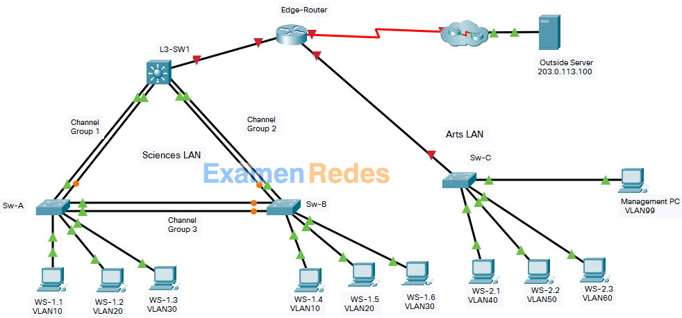
In this assessment you are configuring a network that is using EtherChannel and routing between VLANs. For the sake of time, you will not be asked to perform all configurations on all network devices as you may be required to do in a real network or other assessment. Instead, you will use the skills and knowledge that you have learned in the labs in this course to configure the router and switches in the topology. In addition to EtherChannel and inter-VLAN routing, this task involves creating VLANs and trunks, and performing basic router and switch configuration.
You are required to configure host default gateways; however host addresses are preconfigured.
You will practice and be assessed on the following skills:
- Configuration of initial settings on a router.
- Configuration of initial settings on a switch, including SVI and SSH.
- Configuration of VLANs.
- Configuration of switchport VLAN membership.
- EtherChannel configuration.
- Troubleshooting VLANs.
- Configuration of static trunking and DTP.
- Configuration of routing between VLANs on a Layer 3 switch.
- Configuration of router-on-a-stick inter- VLAN routing on a router.
- Configure default gateways on hosts.
Addressing Table
| Device | Interface | IP Address | Subnet Mask |
|---|---|---|---|
| Edge-Router | G0/0/0 | 192.168.0.1 | 255.255.255. 0 |
| G0/0/1.40 | 192.168.40.1 | 255.255.255.0 | |
| G0/0/1.50 | 192.168.50.1 | 255.255.255.0 | |
| G0/0/1.60 | 192.168.60.1 | 255.255.255.0 | |
| G0/0/1.99 | 192.168.99.17 | 255.255.255.240 | |
| S0/1/0 | 209.165.201.2 | 255.255.255.252 | |
| L3-SW1 | G1/1/1 | 192.168.0.2 | 255.255.255.0 |
| VLAN10 | 192.168.10.1 | 255.255.255.0 | |
| VLAN20 | 192.168.20.1 | 255.255.255.0 | |
| VLAN30 | 192.168.30.1 | 255.255.255.0 | |
| VLAN99 | 192.168.99.2 | 255..255.255.240 | |
| Sw-C | VLAN99 | 192.168.99.18 | 255.255.255.240 |
| WS-1.1 | NIC | 192.168.10.10 | 255.255.255.0 |
| WS-1.2 | NIC | 192.168.20.20 | 255.255.255.0 |
| WS-1.3 | NIC | 192.168.30.30 | 255.255.255.0 |
| WS-1.4 | NIC | 192.168.10.11 | 255.255.255.0 |
| WS-1.5 | NIC | 192.168.20.21 | 255.255.255.0 |
| WS-1.6 | NIC | 192.168.30.31 | 255.255.255.0 |
| WS-2.1 | NIC | 192.168.40.40 | 255.255.255.0 |
| WS-2.2 | NIC | 192.168.50.50 | 255.255.255.0 |
| WS-2.3 | NIC | 192.168.60.60 | 255.255.255.0 |
| Management PC | NIC | 192.168.99.19 | 255.255.255.0 |
| Outside Server | NIC | 203.0.113.100 | 255.255.255.0 |
Background / Scenario
A corporation is planning to implement EtherChannel and a new VLAN design in order to make the network more efficient. You have been asked to work on a design and prototype of the new network. You have created the logical topology and now need to configure the devices in order to evaluate the design. You will configure VLANs and access port VLAN membership on access layer switches. You will also configure EtherChannel and trunking. Finally, you will configure a router and a Layer 3 switch to route between VLANs. Some addressing had already been configured.
Instructions
Part 1: Basic Router Configuration
Step 1: Configure router Edge-Router with required settings.
a. Open a command window on router Edge-Router and move to privileged EXEC mode.
b. Copy and paste the following configuration into the Edge-Router router CLI.
ip route 192.168.10.0 255.255.255.0 GigabitEthernet0/0/0

ip route 192.168.20.0 255.255.255.0 GigabitEthernet0/0/0

ip route 192.168.30.0 255.255.255.0 GigabitEthernet0/0/0

ip route 192.168.99.0 255.255.255.240 GigabitEthernet0/0/0
Be sure to press the <Enter> key after the last line to return to privileged EXEC mode prompt.
c. Configure the following settings on the router:
- The enable secret password.
- A console password
- Remote access to the VTY lines.
- A banner MOTD message.
- The device hostname according to the value in the addressing table.
- All clear text passwords should be encrypted.
- Interface addressing on G0/0/0 and S0/1/0.
- Interface descriptions on G0/0/0 and S0/1/0.
Router(config)#no ip domain lookup
Router(config)#enable secret class

Router(config)#line console 0
Router(config-line)#password cisco
Router(config-line)#login
Router(config-line)#exit

Router(config)#line vty 0 4
Router(config-line)#password cisco
Router(config-line)#login
Router(config-line)#exit

Router(config)#banner motd #Authorized Access Only!#

Router(config)#hostname Edge-Router

Edge-Router(config)#service password-encryption

Edge-Router(config)#interface g0/0/0
Edge-Router(config-if)#ip address 192.168.0.1 255.255.255.0
Edge-Router(config-if)#no shutdown
Edge-Router(config-if)#description Link to LAN 1
Edge-Router(config-if)#exit

Edge-Router(config)#interface s0/1/0
Edge-Router(config-if)#ip address 209.165.201.2 255.255.255.252
Edge-Router(config-if)#no shutdown
Edge-Router(config-if)#description Link to Internet
Edge-Router(config-if)#exit
Note: Be sure to make a record of the passwords that you create.
Part 2: Basic Switch Configuration
Step 1: Configure Remote Management Addressing
a. Configure SVI 99 on switch Sw-C with IP addressing according to the Addressing Table.
b. The Sw-C switch SVI should be reachable from other networks.
Sw-C(config)#interface vlan 99
Sw-C(config-if)#ip address 192.168.99.18 255.255.255.240
Sw-C(config-if)#no shutdown
Sw-C(config-if)#exit
Sw-C(config)#
Sw-C(config)#ip default-gateway 192.168.99.17
Step 2: Configure Secure Remote Access
On switch Sw-C, configure SSH as follows:
- Username: admin password: C1sco123!
- Modulus bits 1024
- All VTY lines should accept SSH connections only
- Connections should require the previously configured username and password.
- IP domain name: acad.pt
Sw-C(config)#ip domain-name acad.pt
Sw-C(config)#crypto key generate rsa
How many bits in the modulus [512]: 1024

Sw-C(config)#username admin privilege 15 secret C1sco123!
Sw-C(config)#enable secret C1sco123!
Sw-C(config)#line vty 0 15
Sw-C(config-line)#transport input ssh
Sw-C(config-line)#login local
Sw-C(config-line)#exit
Sw-C(config)#ip ssh version 2
Part 3: VLAN Configuration
Step 1: Configure VLANs according to the VLAN table.
Use the VLAN Table to create and name the VLANs on the appropriate switches.
VLAN Table
| VLAN | Name | IP Network | Subnet Mask | Devices |
|---|---|---|---|---|
| 10 | FL1 | 192.168.10.0 | 255.255.255.0 | L3-SW1, Sw-A, |
| Sw-B | ||||
| 20 | FL2 | 192.168.20.0 | 255.255.255.0 | L3-SW1, Sw-A, |
| Sw-B | ||||
| 30 | FL3 | 192.168.30.0 | 255.255.255.0 | L3-SW1, Sw-A, |
| Sw-B | ||||
| 40 | FAC | 192.168.40.0 | 255.255.255.0 | Sw-C |
| 50 | BDG5 | 192.168.50.0 | 255.255.255.0 | Sw-C |
| 60 | BDG6 | 192.168.60.0 | 255.255.255.0 | Sw-C |
| 99 | Management | 192.168.99.16 | 255.255.255.240 | Sw-C, L3-SW1 |
L3-SW1
L3-SW1(config)#vlan 10
L3-SW1(config-vlan)#name FL1
L3-SW1(config-vlan)#interface vlan 10
L3-SW1(config-if)#description FL1
L3-SW1(config-if)#ip address 192.168.10.1 255.255.255.0
L3-SW1(config-if)#exit
L3-SW1(config)#
L3-SW1(config)#vlan 20
L3-SW1(config-vlan)#name FL2
L3-SW1(config-vlan)#interface vlan 20
L3-SW1(config-if)#description FL2
L3-SW1(config-if)#ip address 192.168.20.1 255.255.255.0
L3-SW1(config-if)#exit
L3-SW1(config)#
L3-SW1(config)#vlan 30
L3-SW1(config-vlan)#name FL3
L3-SW1(config-vlan)#interface vlan 30
L3-SW1(config-if)#description FL3
L3-SW1(config-if)#ip address 192.168.30.1 255.255.255.0
L3-SW1(config-if)#exit
L3-SW1(config)#
L3-SW1(config)#vlan 99
L3-SW1(config-vlan)#name Management
L3-SW1(config-vlan)#interface vlan 99
L3-SW1(config-if)#description Management
L3-SW1(config-if)#ip address 192.168.99.2 255.255.255.240
L3-SW1(config-if)#exit
Sw-A
Sw-A(config)#vlan 10
Sw-A(config-vlan)#name FL1
Sw-A(config-vlan)#interface vlan 10
Sw-A(config-if)#description FL1
Sw-A(config-if)#exit
Sw-A(config)#
Sw-A(config)#vlan 20
Sw-A(config-vlan)#name FL2
Sw-A(config-vlan)#interface vlan 20
Sw-A(config-if)#description FL2
Sw-A(config-if)#exit
Sw-A(config)#
Sw-A(config)#vlan 30
Sw-A(config-vlan)#name FL3
Sw-A(config-vlan)#interface vlan 30
Sw-A(config-if)#description FL3
Sw-A(config-if)#exit
Sw-B
Sw-B(config)#vlan 10
Sw-B(config-vlan)#name FL1
Sw-B(config-vlan)#interface vlan 10
Sw-B(config-if)#description FL1
Sw-B(config-if)#exit
Sw-B(config)#
Sw-B(config)#vlan 20
Sw-B(config-vlan)#name FL2
Sw-B(config-vlan)#interface vlan 20
Sw-B(config-if)#description FL2
Sw-B(config-if)#exit
Sw-B(config)#
Sw-B(config)#vlan 30
Sw-B(config-vlan)#name FL3
Sw-B(config-vlan)#interface vlan 30
Sw-B(config-if)#description FL3
Sw-B(config-if)#exit
Sw-C
Sw-C(config)#vlan 40
Sw-C(config-vlan)#name BDG4
Sw-C(config-vlan)#interface vlan 40
Sw-C(config-if)#ip address 192.168.40.1 255.255.255.0
Sw-C(config-if)#description BDG4
Sw-C(config-if)#exit
Sw-C(config)#
Sw-C(config)#vlan 50
Sw-C(config-vlan)#name BDG5
Sw-C(config-vlan)#interface vlan 50
Sw-C(config-if)#ip address 192.168.50.1 255.255.255.0
Sw-C(config-if)#description BDG5
Sw-C(config-if)#exit
Sw-C(config)#
Sw-C(config)#vlan 60
Sw-C(config-vlan)#name BDG6
Sw-C(config-vlan)#interface vlan 60
Sw-C(config-if)#ip address 192.168.60.1 255.255.255.0
Sw-C(config-if)#description BDG6
Sw-C(config-if)#exit
Sw-C(config)#
Sw-C(config)#vlan 99
Sw-C(config-vlan)#name Management
Sw-C(config-vlan)#interface vlan 99
Sw-C(config-if)#ip address 192.168.99.18 255.255.255.240
Sw-C(config-if)#description Management
Sw-C(config-if)#exit
Step 2: Assign switch ports to VLANs.
Assign VLAN membership to static access switchports according to the Port to VLAN Assignment table.
Port to VLAN Assignment Table
| Device | VLAN | VLAN Name | Port Assignments |
|---|---|---|---|
| Sw-A | 10 | FL1 | F0/7-10 |
| 20 | FL2 | F0/11-15 | |
| 30 | FL3 | F0/16-24 | |
| Sw-B | 10 | FL1 | F0/7-10 |
| 20 | FL2 | F0/11-15 | |
| 30 | FL3 | F0/16-24 | |
| Sw-C | 40 | FAC | F0/1-5 |
| 50 | BDG5 | F0/6-10 | |
| 60 | BDG6 | F0/11-15 | |
| 99 | Management Native | F0/24 |
Sw-A
Sw-A(config)#interface range f0/7-10
Sw-A(config-if-range)#switchport mode access
Sw-A(config-if-range)#switchport access vlan 10
Sw-A(config-if-range)#exit
Sw-A(config)#interface range f0/11-15
Sw-A(config-if-range)#switchport mode access
Sw-A(config-if-range)#switchport access vlan 20
Sw-A(config-if-range)#exit
Sw-A(config)#interface range f0/16-24
Sw-A(config-if-range)#switchport mode access
Sw-A(config-if-range)#switchport access vlan 30
Sw-A(config-if-range)#exit
Sw-B
Sw-B(config)#interface range f0/7-10
Sw-B(config-if-range)#switchport mode access
Sw-B(config-if-range)#switchport access vlan 10
Sw-B(config-if-range)#exit
Sw-B(config)#interface range f0/11-15
Sw-B(config-if-range)#switchport mode access
Sw-B(config-if-range)#switchport access vlan 20
Sw-B(config-if-range)#exit
Sw-B(config)#interface range f0/16-24
Sw-B(config-if-range)#switchport mode access
Sw-B(config-if-range)#switchport access vlan 30
Sw-B(config-if-range)#exit
Sw-C
Sw-C(config)#interface range f0/1-5
Sw-C(config-if-range)#switchport mode access
Sw-C(config-if-range)#switchport access vlan 40
Sw-C(config-if-range)#exit
Sw-C(config)#interface range f0/6-10
Sw-C(config-if-range)#switchport mode access
Sw-C(config-if-range)#switchport access vlan 50
Sw-C(config-if-range)#exit
Sw-C(config)#interface range f0/11-15
Sw-C(config-if-range)#switchport mode access
Sw-C(config-if-range)#switchport access vlan 60
Sw-C(config-if-range)#exit
Sw-C(config)#interface f0/24
Sw-C(config-if)#switchport mode access
Sw-C(config-if)#switchport access vlan 99
Sw-C(config-if)#exit
Part 4: EtherChannel and Trunking Configuration
EtherChannel Port Assignments Table
| Channel Group | Devices in Groups | Ports in Group |
|---|---|---|
| 1 | L3-SW1 | G1/0/1, G1/0/2 |
| Sw-A | G0/1, G0/2 | |
| 2 | L3-SW1 | G1/0/3, G1/0/4 |
| Sw-B | G0/1, G0/2 | |
| 3 | Sw-A | F0/5, F0/6 |
| Sw-B | F0/5, F0/6 |
Step 1: Configure EtherChannels
Create EtherChannels according to the EtherChannel Port Assignments Table. Use the Cisco LACP protocol. Both sides of the channel should attempt to negotiate the link protocol.
L3-SW1
L3-SW1(config)#interface range g1/0/1-2
L3-SW1(config-if-range)#channel-group 1 mode active
L3-SW1(config-if-range)#exit
L3-SW1(config)#
L3-SW1(config)#interface range g1/0/3-4
L3-SW1(config-if-range)#channel-group 2 mode active
L3-SW1(config-if-range)#exit
Sw-A
Sw-A(config)#interface range g0/1-2
Sw-A(config-if-range)#channel-group 1 mode active
Sw-A(config-if-range)#exit
Sw-A(config)#
Sw-A(config)#interface range f0/5-6
Sw-A(config-if-range)#channel-group 3 mode active
Sw-A(config-if-range)#exit
Sw-B
Sw-B(config)#interface range g0/1-2
Sw-B(config-if-range)#channel-group 2 mode active
Sw-B(config-if-range)#exit
Sw-B(config)#
Sw-B(config)#interface range f0/5-6
Sw-B(config-if-range)#channel-group 3 mode active
Sw-B(config-if-range)#exit
Step 2: Configure Trunking on the EtherChannels
a. Configure the port channel interfaces as static trunks. Disable DTP negotiation on all trunks.
b. Troubleshoot any issues that prevent the formation of the EtherChannels.
L3-SW1
L3-SW1(config)#interface port-channel 1
L3-SW1(config-if)#switchport mode trunk
L3-SW1(config-if)#switchport trunk allowed vlan 10,20,30
L3-SW1(config-if)#exit
L3-SW1(config)#
L3-SW1(config)#interface port-channel 2
L3-SW1(config-if)#switchport mode trunk
L3-SW1(config-if)#switchport trunk allowed vlan 10,20,30
L3-SW1(config-if)#exit
Sw-A
Sw-A(config)#interface port-channel 1
Sw-A(config-if)#switchport mode trunk
Sw-A(config-if)#switchport nonegotiate
Sw-A(config-if)#exit
Sw-A(config)#
Sw-A(config)#interface port-channel 3
Sw-A(config-if)#switchport mode trunk

Sw-A(config-if)#switchport nonegotiate
Sw-A(config-if)#exit
Sw-B
Sw-B(config)#interface port-channel 2
Sw-B(config-if)#switchport mode trunk
Sw-B(config-if)#switchport nonegotiate
Sw-B(config-if)#exit
Sw-B(config)#
Sw-B(config)#interface port-channel 3
Sw-B(config-if)#switchport mode trunk

Sw-B(config-if)#switchport nonegotiate
Sw-B(config-if)#exit
Note: Packet Tracer requires configuration of trunking and DTP mode on both portchannel interfaces and the component physical interfaces.
Step 3: Configure a static trunk uplink
a. On the Sw-C switch, configure the port that is connected to Edge-Router G0/0/0 as a static trunk.
b. Configure the Management VLAN as the native VLAN.
c. Disable DTP on the port.
Sw-C
Sw-C(config)#interface g0/1
Sw-C(config-if)#switchport mode trunk
Sw-C(config-if)#switchport nonegotiate
Sw-C(config-if)#switchport trunk native vlan 99
Sw-C(config-if)#switchport trunk allowed vlan 40,50,60,99
Sw-C(config-if)#exit
Part 5: Configure Inter-VLAN Routing
Step 1: Configure inter-VLAN routing on the Layer 3 switch.
a. Configure Inter-VLAN routing on the L3-SW1 Layer 3 switch for all VLANs in the VLAN Table that are configured on L3-SW1.
b. Configure the switchport on L3-SW1 that is connected to Edge-Router with an IP address as shown in the Addressing Table.
L3-SW1
L3-SW1(config)#ip routing
L3-SW1(config)#interface g1/1/1
L3-SW1(config-if)#no switchport
L3-SW1(config-if)#ip address 192.168.0.2 255.255.255.0
Step 2: Configure router-on-a-stick inter-VLAN routing on a router.
a. Configure inter-VLAN routing on Edge-Router for all the VLANs that are configured on the Sw-C switch. Use the information in the Addressing Table.
b. Be sure to configure descriptions of all interfaces.
Edge-Router
Edge-Router(config)#interface g0/0/1
Edge-Router(config-if)#no shutdown
Edge-Router(config)#interface g0/0/1.40
Edge-Router(config-subif)#description "Gateway for VLAN40"
Edge-Router(config-subif)#encapsulation dot1q 40
Edge-Router(config-subif)#ip address 192.168.40.1 255.255.255.0
Edge-Router(config-subif)#exit
Edge-Router(config)#interface g0/0/1.50
Edge-Router(config-subif)#description "Gateway for VLAN50"
Edge-Router(config-subif)#encapsulation dot1q 50
Edge-Router(config-subif)#ip address 192.168.50.1 255.255.255.0
Edge-Router(config-subif)#exit
Edge-Router(config)#interface g0/0/1.60
Edge-Router(config-subif)#description "Gateway for VLAN60"
Edge-Router(config-subif)#encapsulation dot1q 60
Edge-Router(config-subif)#ip address 192.168.60.1 255.255.255.0
Edge-Router(config-subif)#exit
Edge-Router(config)#interface g0/0/1.99
Edge-Router(config-subif)#description "Gateway for VLAN99"
Edge-Router(config-subif)#encapsulation dot1q 99 native
Edge-Router(config-subif)#ip address 192.168.99.17 255.255.255.240
Edge-Router(config-subif)#exit
Step 3: Configure default gateways on hosts.
a. Configure default gateway addresses on all hosts on the LANs.
Default gateway on WS-1.2 and WS-1.5: 192.168.20.1
Default gateway on WS-1.3 and WS-1.6: 192.168.30.1
Default gateway on WS-2.1: 192.168.40.1
Default gateway on WS-2.2: 192.168.50.1
Default gateway on WS-2.3: 192.168.60.1
Default gateway on Management PC: 192.168.99.17
c. Verify that a host can connect to the SVI of switch Sw-C over SSH.
Last Updated: January 2021
ID 211
Intructions – Answers
Router Edge-Router
en
conf t
ip route 192.168.10.0 255.255.255.0 GigabitEthernet0/0/0
ip route 192.168.20.0 255.255.255.0 GigabitEthernet0/0/0
ip route 192.168.30.0 255.255.255.0 GigabitEthernet0/0/0
ip route 192.168.99.0 255.255.255.240 GigabitEthernet0/0/0
no ip domain lookup

enable secret class
line console 0
password cisco
login
exit
line vty 0 4
password cisco
login
exit
banner motd #Authorized Access Only!#
hostname Edge-Router
service password-encryption
interface g0/0/0
ip address 192.168.0.1 255.255.255.0
no shutdown
description "R1 G0/0/0"
exit
interface s0/1/0
ip address 209.165.201.2 255.255.255.252
no shutdown
description "R1 S0/1/0"
exit

interface g0/0/1
no shutdown

interface g0/0/1.40
description "Gateway for VLAN40"
encapsulation dot1q 40
ip address 192.168.40.1 255.255.255.0
exit
interface g0/0/1.50
description "Gateway for VLAN50"
encapsulation dot1q 50
ip address 192.168.50.1 255.255.255.0
exit
interface g0/0/1.60
description "Gateway for VLAN60"
encapsulation dot1q 60
ip address 192.168.60.1 255.255.255.0
exit
interface g0/0/1.99
description "Gateway for VLAN99"
encapsulation dot1q 99 native
ip address 192.168.99.17 255.255.255.240
end
copy running-config startup-config
Switch Sw-C
en
config t
interface vlan 99
ip address 192.168.99.18 255.255.255.240
no shutdown
exit
ip default-gateway 192.168.99.17
ip domain-name acad.pt
crypto key generate rsa
1024

username admin privilege 15 secret C1sco123!
enable secret C1sco123!
line vty 0 15
transport input ssh
login local
exit
ip ssh version 2

vlan 40
name BDG4
exit
interface vlan 40
ip address 192.168.40.1 255.255.255.0
description BDG4
exit
vlan 50
name BDG5
exit
interface vlan 50
ip address 192.168.50.1 255.255.255.0
description BDG5
exit
vlan 60
name BDG6
exit
interface vlan 60
ip address 192.168.60.1 255.255.255.0
description BDG6
exit
vlan 99
name Management
exit
interface vlan 99
ip address 192.168.99.18 255.255.255.240
description Management
exit

interface range f0/1-5
switchport mode access
switchport access vlan 40
exit
interface range f0/6-10
switchport mode access
switchport access vlan 50
exit
interface range f0/11-15
switchport mode access
switchport access vlan 60
exit
interface f0/24
switchport mode access
switchport access vlan 99
exit
interface g0/1
switchport mode trunk
switchport nonegotiate
switchport trunk allowed vlan 40,50,60,99
switchport trunk native vlan 99
end
copy running-config startup-config
Switch L3-SW1
en
config t
vlan 10
name FL1
interface vlan 10
description FL1
ip address 192.168.10.1 255.255.255.0
exit
vlan 20
name FL2
interface vlan 20
description FL2
ip address 192.168.20.1 255.255.255.0
exit
vlan 30
name FL3
interface vlan 30
description FL3
ip address 192.168.30.1 255.255.255.0
exit
vlan 99
name Management
interface vlan 99
description Management
ip address 192.168.99.2 255.255.255.240
exit

ip routing
interface g1/1/1
no switchport
ip address 192.168.0.2 255.255.255.0
exit

interface range g1/0/1-2
channel-group 1 mode active
exit
interface port-channel 1
switchport mode trunk
switchport trunk allowed vlan 10,20,30
exit
interface range g1/0/3-4
channel-group 2 mode active
exit
interface port-channel 2
switchport mode trunk
switchport trunk allowed vlan 10,20,30
end
copy running-config startup-config
Switch Sw-A
enable
config terminal
vlan 10
name FL1
interface vlan 10
description FL1
exit
vlan 20
name FL2
interface vlan 20
description FL2
exit
vlan 30
name FL3
interface vlan 30
description FL3
exit

interface range f0/7-10
switchport mode access
switchport access vlan 10
exit
interface range f0/11-15
switchport mode access
switchport access vlan 20
exit
interface range f0/16-24
switchport mode access
switchport access vlan 30
exit

interface range g0/1-2
channel-group 1 mode active
exit
interface port-channel 1
switchport mode trunk
switchport nonegotiate
exit
interface range f0/5-6
channel-group 3 mode active
exit
interface port-channel 3
switchport mode trunk
switchport nonegotiate
end
copy running-config startup-config
Switch Sw-B
en
config t
vlan 10
name FL1
interface vlan 10
description FL1
exit
vlan 20
name FL2
interface vlan 20
description FL2
exit
vlan 30
name FL3
interface vlan 30
description FL3
exit

interface range f0/7-10
switchport mode access
switchport access vlan 10
exit
interface range f0/11-15
switchport mode access
switchport access vlan 20
exit
interface range f0/16-24
switchport mode access
switchport access vlan 30
exit

interface range g0/1-2
channel-group 2 mode active
exit
interface port-channel 2
switchport mode trunk
switchport nonegotiate
exit
interface range f0/5-6
channel-group 3 mode active
exit
interface port-channel 3
switchport mode trunk
switchport nonegotiate
end
copy running-config startup-config
Configure default gateway addresses on all hosts on the LANs.
Default gateway on WS-1.2 and WS-1.5: 192.168.20.1
Default gateway on WS-1.3 and WS-1.6: 192.168.30.1
Default gateway on WS-2.1: 192.168.40.1
Default gateway on WS-2.2: 192.168.50.1
Default gateway on WS-2.3: 192.168.60.1
Default gateway on Management PC: 192.168.99.17