Última actualización: septiembre 24, 2021
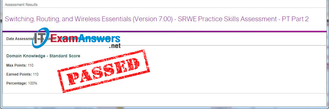
Switching, Routing, and Wireless Essentials ( Versión 7.00) – SRWE Practice PT Skills Assessment (PTSA) – Part 2
Evaluación de habilidades prácticas de PT (PTSA) SRWE – Parte 2 Respuestas
- ID 1
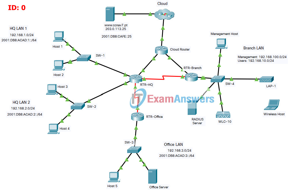
- ID 0
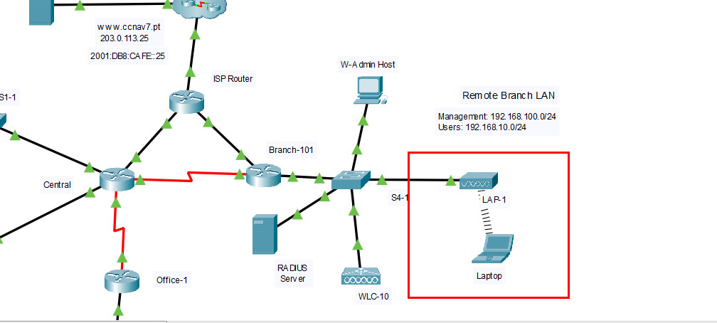
Final Packet Tracer Skills Assessment – Part 2
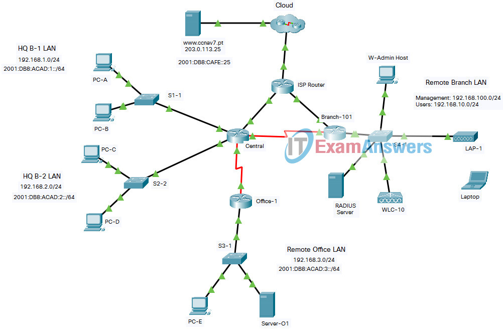
Addressing Table
| Device | Interface | Address and Prefix |
|---|---|---|
| Central | G0/0/0 | 192.168.1.1/24 |
| 2001:db8:acad:1::1/64 | ||
| fe80::1 | ||
| G0/0/1 | 192.168.2.1/24 | |
| 2001:db8:acad:2::1/64 | ||
| fe80::1 | ||
| G0/0/2 | 10.1.0.1/30 | |
| 2001:db8:acad:a::1/64 | ||
| fe80::2 | ||
| S0/1/0 | 10.2.0.1/30 | |
| 2001:db8:acad:b::1/64 | ||
| fe80::2 | ||
| S0/1/1 | 10.4.0.1/30 | |
| 2001:db8:acad:d::1/64 | ||
| Office-1 | S0/1/1 | 10.4.0.2/30 |
| 2001:db8:acad:d::2/64 | ||
| fe80::2 | ||
| G0/0/0 | 192.168.3.1/24 | |
| 2001:db8:acad:3::1/64 | ||
| fe80::1 | ||
| Branch-101 | G0/0/0.10 | 192.168.10.1/24 |
| G0/0/0.100 | 192.168.100.1/24 | |
| G0/0/0.172 | 172.16.1.1/24 | |
| G0/0/1 | DHCP | |
| 2001:db8:acad:c::2/64 | ||
| S0/1/0 | 10.2.0.2/30 | |
| 2001:db8:acad:b::2/64 | ||
| ISP Router | G0/0/0 | 10.1.0.2/24 |
| 2001:DB8:ACAD:A::2/64 | ||
| G0/0/1 | 10.3.0.1/24 | |
| 2001:DB8:ACAD:C::1/64 | ||
| WLC-10 | management | 192.168.100.254 |
| WLAN 10 | 192.168.10.254/24 | |
| Server-O1 | NIC | 192.168.3.122 |
| 2001:db8:acad:3::122 | ||
| Internet Server | NIC | 203.0.113.25 |
| 2001:db8:acad:cafe:25 | ||
| DNS Server | NIC | 198.51.100.163 |
| 2001:DB8:face::163 | ||
| Management Host | NIC | 192.168.100.23 |
| Wireless Host | NIC | DHCP |
| RADIUS server | NIC | 172.16.1.100/24 |
| PC-A | NIC | 192.168.1.10/24 |
| 2001:db8:acad:1::10/64 | ||
| PC-B | NIC | 192.168.1.11/24 |
| 2001:db8:acad:1::11/64 | ||
| PC-C | NIC | 192.168.2.20/24 |
| 2001:db8:acad:2::20/64 | ||
| PC-D | NIC | 192.168.2.11/24 |
| 2001:db8:acad:2::21/64 | ||
| PC-E | NIC | 192.168.3.30/24 |
| 2001:db8:acad:3::30/64 |
Objectives
In this assessment, you will configure the following:
- Floating static and default routes in IPv4 and IPv6.
- Host routes in IPv4 and IPv6.
- DHCP pools and scopes.
- Switch security including port security.
- Enhanced LAN security with DHCP snooping, dynamic ARP inspection, PortFast, and BPDU guard.
- Wireless LAN Controller-based wireless LAN with enterprise authentication.
You will only configure the Central and Branch-101 routers, the S1-1 switch, and the WLC-10 wireless LAN controller. Access to other devices is not available.
Background / Scenario
Netacad PLC is reworking their network. You have been asked to prototype the network in Packet Tracer for evaluation by senior network staff.
Instructions
Part 1: Configure Switch Security
In this part of the assessment you will configure switch S1-1 with switch security features. Switch ports FastEthernet0/1 to FastEthernet0/5 are the active switch ports. Port GigabitEthernet0/1 is a dedicated link to router Central. All other ports should be secured.
Step 1: Configure VLANs
- a. Configure VLAN 10 with name users.
- b. Configure VLAN 999 with the name unused.
S1-1 Switch
S1-1(config)#vlan 10
S1-1(config-vlan)#name users
S1-1(config-vlan)#vlan 999
S1-1(config-vlan)#name unused
Step 2: Configure active switch ports.
On the active switch ports configure the following:
a. Configure FastEthernet 0/1 through 0/5 and GigabitEthernet 0/1 as static access ports in VLAN 10.
S1-1(config)#interface range f0/1-5, g0/1
S1-1(config-if-range)#switchport mode access
S1-1(config-if-range)#switchport access vlan 10
b. Activate port security on the ports.
- Configure the active ports to accept a maximum of 4 MAC addresses.
- If a violation occurs, configure the ports to drop frames from the unauthorized MAC address, log it, and send an alert.
- MAC addresses should be present in the MAC address table for a maximum of 10 minutes before they are removed.
- Ports should add the learned MAC addresses to the running configuration.
- Configure the MAC address of PC-A as a static address on port FastEthernet0/1.
S1-1(config)#interface range f0/1-5
S1-1(config-if-range)#switchport port-security
S1-1(config-if-range)#switchport port-security maximum 4
S1-1(config-if-range)#switchport port-security violation restrict
S1-1(config-if-range)#switchport port-security aging time 10
S1-1(config-if-range)#switchport port-security mac-address sticky
S1-1(config-if-range)#exit

S1-1(config)#interface f0/1
S1-1(config-if)#switchport port-security mac-address 00D0.D3DC.2825
S1-1(config-if)#exit
c. Protect against DHCP snooping.
Note: In this simulated network, DHCP snooping may not operate correctly in Packet Tracer. Configure it as you would normally. You will receive full credit for a configuration that meets the requirements below.
- Activate DHCP snooping globally.
- Activate DHCP snooping for the two VLANs that you configured.
- Configure the ports to limit the rate to 5 DHCP packets per second.
- Configure the port that links to the router as trusted.
S1-1(config)#ip dhcp snooping
S1-1(config)#ip dhcp snooping vlan 10,999
S1-1(config)#interface range f0/1-5, g0/1
S1-1(config-if-range)#ip dhcp snooping limit rate 5
S1-1(config-if-range)#exit
S1-1(config)#interface g0/1
S1-1(config-if)#ip dhcp snooping trust
S1-1(config-if)#exit
d. Guard against ARP attacks by implementing DAI.
- Activate DAI globally.
- Activate DAI on the two VLANs.
- Configure the port that links to the router as trusted.
S1-1(config)#ip arp inspection vlan 10,999
S1-1(config)#interface g0/1
S1-1(config-if)#ip arp inspection trust
S1-1(config-if)#exit
e. Mitigate STP attacks by configuring BPDUguard and PortFast on the active ports.
S1-1(config)#interface range f0/1-5
S1-1(config-if-range)#spanning-tree portfast
S1-1(config-if-range)#spanning-tree bpduguard enable
Step 3: Secure unused switch ports.
a. Move all unused switch ports to VLAN 999.
b. Configure all unused switch ports as static access ports.
c. Deactivate all unused switch ports.
S1-1(config)#interface range f0/6-24, g0/2
S1-1(config-if-range)#switchport mode access
S1-1(config-if-range)#switchport access vlan 999
S1-1(config-if-range)#shutdown
Part 2: Configure Addressing and DHCP
You will configure DHCP and interface addressing on router Branch-101 to prepare for implementing the wireless LAN controller network.
Step 1: Configure and address a subinterface for the WLAN user network.
a. Configure subinterface 10 on the router interface that is connected to the switch S4-1.
b. The router should provide router-on-a-stick routing to VLAN 10.
c. Configure the subinterface with the address from the Addressing Table.
Brand-101 Router
Branch-101(config)#interface g0/0/0.10
Branch-101(config-subif)#description WLAN users
Branch-101(config-subif)#encapsulation dot1q 10
Branch-101(config-subif)#ip address 192.168.10.1 255.255.255.0
Step 2: Configure a DHCP pool for WLAN user network.
a. Exclude the router interface address and the management address of the WLC.
Branch-101(config)#ip dhcp excluded-address 192.168.10.1
Branch-101(config)#ip dhcp excluded-address 192.168.10.254
b. Configure a DHCP pool that will be used by hosts that are connecting to the WLAN.
- Name the pool WLAN-hosts.
- Configure the pool to use addresses in the 192.168.10.0/24 network.
- The pool should also provide the default gateway and DNS server addresses.
Branch-101(config)#ip dhcp pool WLAN-hosts
Branch-101(dhcp-config)#network 192.168.10.0 255.255.255.0
Branch-101(dhcp-config)#default-router 192.168.10.1
Branch-101(dhcp-config)#dns-server 198.51.100.163
Step 3: Configure an interface as a DHCP client.
On Branch-101, configure the interface that is connected to ISP Router to receive its address over DHCP.
Branch-101(config)#interface g0/0/1
Branch-101(config-if)#ip address dhcp
Branch-101(config-if)#exit
Part 3: Configure Static Routes
In this part of the assessment you will configure static, default, floating static, and host routes in both IPv4 and IPv6. You will configure the Central and Branch-101 routers. Netacad PLC has decided that it wants to use static routing between all its networks. In addition, the company wants to use the Ethernet links between routers for most data traffic and reserve serial link between Central and Branch-101 for backup purposes in case one of the Ethernet links becomes unavailable. You will be configuring floating static and default routes.
Step 1: Configure static routes on Central.
a. Configure IPv4 default routes to the cloud using the Ethernet link as the preferred link and the serial link as the floating backup. Use an administrative distance of 10 for the backup route. These routes should be configured as directly connected routes.
Note: Ethernet interfaces will give a warning when configured without a next-hop address. In this configuration, the interface is point-to-point, so the warning can be ignored.
Central(config)#ip route 0.0.0.0 0.0.0.0 g0/0/2
Central(config)#ip route 0.0.0.0 0.0.0.0 s0/1/0 10
b. Configure IPv4 static routes to the Remote Branch LAN WLAN user network following the same guidelines as above for type of route and administrative distance.
Central(config)#ip route 192.168.10.0 255.255.255.0 g0/0/2
Central(config)#ip route 192.168.10.0 255.255.255.0 s0/1/0 10
c. Configure an IPv4 host route on Central to the Server-O1 on the Remote Office LAN. Create a directly connected route.
Central(config)#ip route 192.168.3.122 255.255.255.255 s0/1/1
Note: For the purpose of this assessment, please enter the IPv4 static routes in the following order:
1) IPv4 default route
2) IPv4 floating default route
3) IPv4 host route
4) IPv4 static route to Remote Branch LAN
5) IPv4 floating static route to Remote Branch LAN
d. Ensure that the device is configured to route IPv6.
e. Configure IPv6 default routes to the cloud. Use the Ethernet link as the primary route, and the serial link as the floating backup. Use an administrative distance of 10 for the backup route. These routes should specify the next hop interface address.
Central(config)#ipv6 unicast-routing
Central(config)#ipv6 route ::/0 2001:DB8:ACAD:A::2
Central(config)#ipv6 route ::/0 2001:db8:acad:b::2 10
f. Configure an IPv6 host route on Central to the Server-O1 on the Remote Office LAN It should be a next-hop route.
Central(config)#ipv6 route 2001:db8:acad:3::122/128 2001:db8:acad:d::2
Note: For the purpose of this assessment, please enter the IPv6 static routes in the following order:
1) IPv6 default route
2) IPv6 floating default route
3) IPv6 host route
Step 2: Configure static routes on Branch-101.
Branch-101 must also be configured with static routes to the other three networks in the Netacad PLC network. It will require floating static and default routes in IPv4 and IPv6 following the same guidelines as were used for the Central static routes.
- IPv6 routes use next-hop address arguments.
- IPv4 routes use exit interface arguments.
- All routes should prefer the Ethernet links over the serial link.
- Backup floating routes use an administrative distance of 10.
a. Configure IPv4 default routes to the cloud using the Ethernet link as the preferred link and the serial link as the backup.
Note: For the purpose of this assessment, please enter the IPv4 static routes in the following order:
1) IPv4 default route
2) IPv4 floating default route
Branch-101(config)#ip route 0.0.0.0 0.0.0.0 g0/0/1
Branch-101(config)#ip route 0.0.0.0 0.0.0.0 s0/1/0 10
b. Ensure that the device is configured to route IPv6.
c. Configure IPv6 default routes to the cloud. Use the Ethernet link as the primary route, and the serial link as backup. Use an administrative distance of 10 for the backup route. These routes should specify the next hop interface address.
Branch-101(config)#ipv6 unicast-routing
Branch-101(config)#ipv6 route ::/0 2001:DB8:ACAD:C::1
Branch-101(config)#ipv6 route ::/0 2001:DB8:ACAD:B::1 10
Note: For the purpose of this assessment, please enter the IPv6 static routes in the following order:
1) IPv6 default route
2) IPv6 floating default route
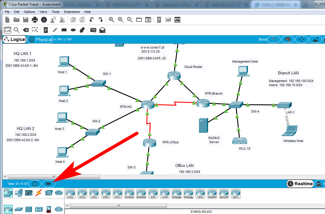
Final Packet Tracer Skills Assessment – Part 2
Addressing Table
| Device | Interface | Address and Prefix |
|---|---|---|
| RTR-HQ | G0/0/0 | 192.168.1.1/24 |
| 2001:db8:acad:1::1/64 | ||
| fe80::1 | ||
| G0/0/1 | 192.168.2.1/24 | |
| 2001:db8:acad:2::1/64 | ||
| fe80::1 | ||
| G0/0/2 | 10.1.0.1/30 | |
| 2001:db8:acad:a::1/64 | ||
| fe80::2 | ||
| S0/1/0 | 10.2.0.1/30 | |
| 2001:db8:acad:b::1/64 | ||
| fe80::2 | ||
| S0/1/1 | 10.4.0.1/30 | |
| 2001:db8:acad:d::1/64 | ||
| RTR-Office | S0/1/1 | 10.4.0.2/30 |
| 2001:db8:acad:d::2/64 | ||
| fe80::2 | ||
| G0/0/0 | 192.168.3.1/24 | |
| 2001:db8:acad:3::1/64 | ||
| fe80::1 | ||
| RTR-Branch | G0/0/0.10 | 192.168.10.1/24 |
| G0/0/0.100 | 192.168.100.1/24 | |
| G0/0/0.172 | 172.16.1.1/24 | |
| G0/0/1 | DHCP | |
| 2001:db8:acad:c::2/64 | ||
| S0/1/0 | 10.2.0.2/30 | |
| 2001:db8:acad:b::2/64 | ||
| Cloud Router | G0/0/0 | 10.1.0.2/24 |
| 2001:DB8:ACAD:A::2/64 | ||
| G0/0/1 | 10.3.0.1/24 | |
| 2001:DB8:ACAD:C::1/64 | ||
| WLC-10 | management | 192.168.100.254 |
| WLAN 10 | 192.168.10.254/24 | |
| Office Server | NIC | 192.168.3.122 |
| 2001:db8:acad:3::122 | ||
| Web Server | NIC | 203.0.113.25 |
| 2001:db8:acad:cafe:25 | ||
| DNS Server | NIC | 198.51.100.163 |
| 2001:DB8:face::163 | ||
| Management Host | NIC | 192.168.100.23 |
| Wireless Host | NIC | DHCP |
| RADIUS server | NIC | 172.16.1.100/24 |
| Host 1 | NIC | 192.168.1.10/24 |
| 2001:db8:acad:1::10/64 | ||
| Host 2 | NIC | 192.168.1.11/24 |
| 2001:db8:acad:1::11/64 | ||
| Host 3 | NIC | 192.168.2.20/24 |
| 2001:db8:acad:2::20/64 | ||
| Host 4 | NIC | 192.168.2.11/24 |
| 2001:db8:acad:2::21/64 | ||
| Host 5 | NIC | 192.168.3.30/24 |
| 2001:db8:acad:3::30/64 |
Objectives
In this assessment, you will configure the following:
- Floating static and default routes in IPv4 and IPv6.
- Host routes in IPv4 and IPv6.
- DHCP pools and scopes.
- Switch security including port security.
- Enhanced LAN security with DHCP snooping, dynamic ARP inspection, PortFast, and BPDU guard.
- Wireless LAN Controller-based wireless LAN with enterprise authentication.
You will only configure the RTR-HQ and RTR-Branch routers, the SW-1 switch, and the WLC-10 wireless LAN controller. Access to other devices is not available.
Background / Scenario
XYZ Corp. is reworking their network. You have been asked to prototype the network in Packet Tracer for evaluation by senior network staff.
Instructions
Part 1: Configure Switch Security
In this part of the assessment you will configure switch SW-1 with switch security features. Switch ports FastEthernet0/1 to FastEthernet0/5 are the active switch ports. Port GigabitEthernet0/1 is a dedicated link to router RTR-HQ. All other ports should be secured.
Step 1: Configure VLANs
- a. Configure VLAN 10 with name users.
- b. Configure VLAN 999 with the name unused.
SW-1 Switch
SW-1(config)#vlan 10
SW-1(config-vlan)#name users
SW-1(config-vlan)#vlan 999
SW-1(config-vlan)#name unused
Step 2: Configure active switch ports.
On the active switch ports configure the following:
a. Configure FastEthernet 0/1 through 0/5 and GigabitEthernet 0/1 as static access ports in VLAN 10.
SW-1(config)#interface range f0/1-5, g0/1
SW-1(config-if-range)#switchport mode access
SW-1(config-if-range)#switchport access vlan 10
b. Activate port security on the ports.
- Configure the active ports to accept a maximum of 4 MAC addresses.
- If a violation occurs, configure the ports to drop frames from the unauthorized MAC address, log it, and send an alert.
- MAC addresses should be present in the MAC address table for a maximum of 10 minutes before they are removed.
- Ports should add the learned MAC addresses to the running configuration.
- Configure the MAC address of Host 1 as a static address on port FastEthernet0/1.
SW-1(config)#interface range f0/1-5
SW-1(config-if-range)#switchport port-security
SW-1(config-if-range)#switchport port-security maximum 4
SW-1(config-if-range)#switchport port-security violation restrict
SW-1(config-if-range)#switchport port-security aging time 10
SW-1(config-if-range)#switchport port-security mac-address sticky
SW-1(config-if-range)#exit

SW-1(config)#interface f0/1
SW-1(config-if)#switchport port-security mac-address 00D0.D3DC.2825
SW-1(config-if)#exit
c. Protect against DHCP snooping.
Note: In this simulated network, DHCP snooping may not operate correctly in Packet Tracer. Configure it as you would normally. You will receive full credit for a configuration that meets the requirements below.
- Activate DHCP snooping globally.
- Activate DHCP snooping for the two VLANs that you configured.
- Configure the ports to limit the rate to 5 DHCP packets per second.
- Configure the port that links to the router as trusted.
SW-1(config)#ip dhcp snooping
SW-1(config)#ip dhcp snooping vlan 10,999
SW-1(config)#interface range f0/1-5, g0/1
SW-1(config-if-range)#ip dhcp snooping limit rate 5
SW-1(config-if-range)#exit
SW-1(config)#interface g0/1
SW-1(config-if)#ip dhcp snooping trust
SW-1(config-if)#exit
d. Guard against ARP attacks by implementing DAI.
- Activate DAI globally.
- Activate DAI on the two VLANs.
- Configure the port that links to the router as trusted.
SW-1(config)#ip arp inspection vlan 10,999
SW-1(config)#interface g0/1
SW-1(config-if)#ip arp inspection trust
SW-1(config-if)#exit
e. Mitigate STP attacks by configuring BPDUguard and PortFast on the active ports.
SW-1(config)#interface range f0/1-5
SW-1(config-if-range)#spanning-tree portfast
SW-1(config-if-range)#spanning-tree bpduguard enable
Step 3: Secure unused switch ports.
a. Move all unused switch ports to VLAN 999.
b. Configure all unused switch ports as static access ports.
c. Deactivate all unused switch ports.
SW-1(config)#interface range f0/6-24, g0/2
SW-1(config-if-range)#switchport mode access
SW-1(config-if-range)#switchport access vlan 999
SW-1(config-if-range)#shutdown
Part 2: Configure Addressing and DHCP
You will configure DHCP and interface addressing on router RTR-Branch to prepare for implementing the wireless LAN controller network.
Step 1: Configure and address a subinterface for the WLAN user network.
a. Configure subinterface 10 on the router interface that is connected to the switch S4-1.
b. The router should provide router-on-a-stick routing to VLAN 10.
c. Configure the subinterface with the address from the Addressing Table.
Brand-101 Router
RTR-Branch(config)#interface g0/0/0.10
RTR-Branch(config-subif)#description WLAN users
RTR-Branch(config-subif)#encapsulation dot1q 10
RTR-Branch(config-subif)#ip address 192.168.10.1 255.255.255.0
Step 2: Configure a DHCP pool for WLAN user network.
a. Exclude the router interface address and the management address of the WLC.
RTR-Branch(config)#ip dhcp excluded-address 192.168.10.1
RTR-Branch(config)#ip dhcp excluded-address 192.168.10.254
b. Configure a DHCP pool that will be used by hosts that are connecting to the WLAN.
- Name the pool WLAN-hosts.
- Configure the pool to use addresses in the 192.168.10.0/24 network.
- The pool should also provide the default gateway and DNS server addresses.
RTR-Branch(config)#ip dhcp pool WLAN-hosts
RTR-Branch(dhcp-config)#network 192.168.10.0 255.255.255.0
RTR-Branch(dhcp-config)#default-router 192.168.10.1
RTR-Branch(dhcp-config)#dns-server 198.51.100.163
Step 3: Configure an interface as a DHCP client.
On RTR-Branch, configure the interface that is connected to Cloud Router to receive its address over DHCP.
RTR-Branch(config)#interface g0/0/1
RTR-Branch(config-if)#ip address dhcp
RTR-Branch(config-if)#exit
Part 3: Configure Static Routes
In this part of the assessment you will configure static, default, floating static, and host routes in both IPv4 and IPv6. You will configure the RTR-HQ and RTR-Branch routers. XYZ Corp. has decided that it wants to use static routing between all its networks. In addition, the company wants to use the Ethernet links between routers for most data traffic and reserve serial link between RTR-HQ and RTR-Branch for backup purposes in case one of the Ethernet links becomes unavailable. You will be configuring floating static and default routes.
Step 1: Configure static routes on RTR-HQ.
a. Configure IPv4 default routes to the cloud using the Ethernet link as the preferred link and the serial link as the floating backup. Use an administrative distance of 10 for the backup route. These routes should be configured as directly connected routes.
Note: Ethernet interfaces will give a warning when configured without a next-hop address. In this configuration, the interface is point-to-point, so the warning can be ignored.
RTR-HQ(config)#ip route 0.0.0.0 0.0.0.0 g0/0/2
RTR-HQ(config)#ip route 0.0.0.0 0.0.0.0 s0/1/0 10
b. Configure IPv4 static routes to the Remote Branch LAN WLAN user network following the same guidelines as above for type of route and administrative distance.
RTR-HQ(config)#ip route 192.168.10.0 255.255.255.0 g0/0/2
RTR-HQ(config)#ip route 192.168.10.0 255.255.255.0 s0/1/0 10
c. Configure an IPv4 host route on RTR-HQ to the Office Server on the Remote Office LAN. Create a directly connected route.
RTR-HQ(config)#ip route 192.168.3.122 255.255.255.255 s0/1/1
Note: For the purpose of this assessment, please enter the IPv4 static routes in the following order:
1) IPv4 default route
2) IPv4 floating default route
3) IPv4 host route
4) IPv4 static route to Remote Branch LAN
5) IPv4 floating static route to Remote Branch LAN
d. Ensure that the device is configured to route IPv6.
e. Configure IPv6 default routes to the cloud. Use the Ethernet link as the primary route, and the serial link as the floating backup. Use an administrative distance of 10 for the backup route. These routes should specify the next hop interface address.
RTR-HQ(config)#ipv6 unicast-routing
RTR-HQ(config)#ipv6 route ::/0 2001:DB8:ACAD:A::2
RTR-HQ(config)#ipv6 route ::/0 2001:db8:acad:b::2 10
f. Configure an IPv6 host route on RTR-HQ to the Office Server on the Remote Office LAN It should be a next-hop route.
RTR-HQ(config)#ipv6 route 2001:db8:acad:3::122/128 2001:db8:acad:d::2
Note: For the purpose of this assessment, please enter the IPv6 static routes in the following order:
1) IPv6 default route
2) IPv6 floating default route
3) IPv6 host route
Step 2: Configure static routes on RTR-Branch.
RTR-Branch must also be configured with static routes to the other three networks in the XYZ Corp. network. It will require floating static and default routes in IPv4 and IPv6 following the same guidelines as were used for the RTR-HQ static routes.
- IPv6 routes use next-hop address arguments.
- IPv4 routes use exit interface arguments.
- All routes should prefer the Ethernet links over the serial link.
- Backup floating routes use an administrative distance of 10.
a. Configure IPv4 default routes to the cloud using the Ethernet link as the preferred link and the serial link as the backup.
Note: For the purpose of this assessment, please enter the IPv4 static routes in the following order:
1) IPv4 default route
2) IPv4 floating default route
RTR-Branch(config)#ip route 0.0.0.0 0.0.0.0 g0/0/1
RTR-Branch(config)#ip route 0.0.0.0 0.0.0.0 s0/1/0 10
b. Ensure that the device is configured to route IPv6.
c. Configure IPv6 default routes to the cloud. Use the Ethernet link as the primary route, and the serial link as backup. Use an administrative distance of 10 for the backup route. These routes should specify the next hop interface address.
RTR-Branch(config)#ipv6 unicast-routing
RTR-Branch(config)#ipv6 route ::/0 2001:DB8:ACAD:C::1
RTR-Branch(config)#ipv6 route ::/0 2001:DB8:ACAD:B::1 10
Note: For the purpose of this assessment, please enter the IPv6 static routes in the following order:
1) IPv6 default route
2) IPv6 floating default route
Part 4: Configure a Wireless LAN using a Wireless LAN Controller
In this part of the assessment, you will configure the wireless LAN controller to provide access wireless access to the network. Username and password are the default admin/admin. Connect to the WLC over HTTPS to the management interface.
Open the browser from the desktop of W-Admin Host or (Management Host). Connect to the IP address of the WLC over HTTPS: https://192.168.100.254
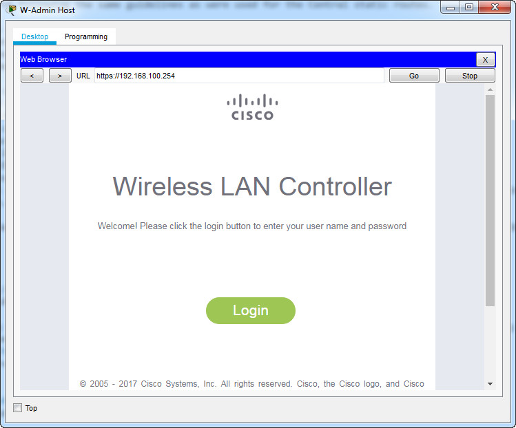
Login with the username admin and password admin
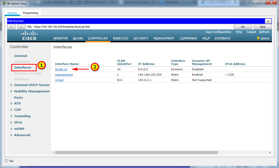
Step 1: Configure a VLAN interface.
a. Create a new interface and name it WLAN 10. The interface should use VLAN 10 and physical port 1.
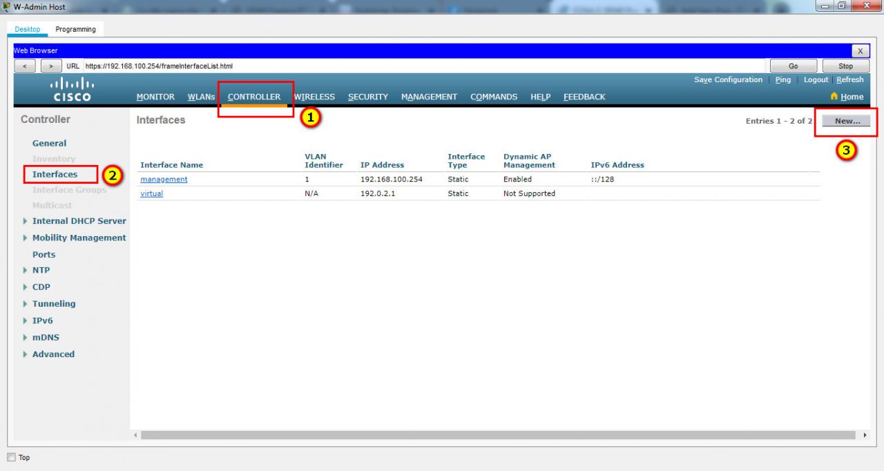
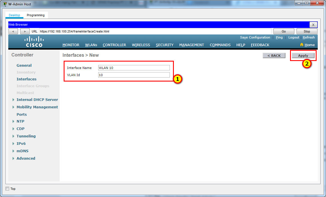
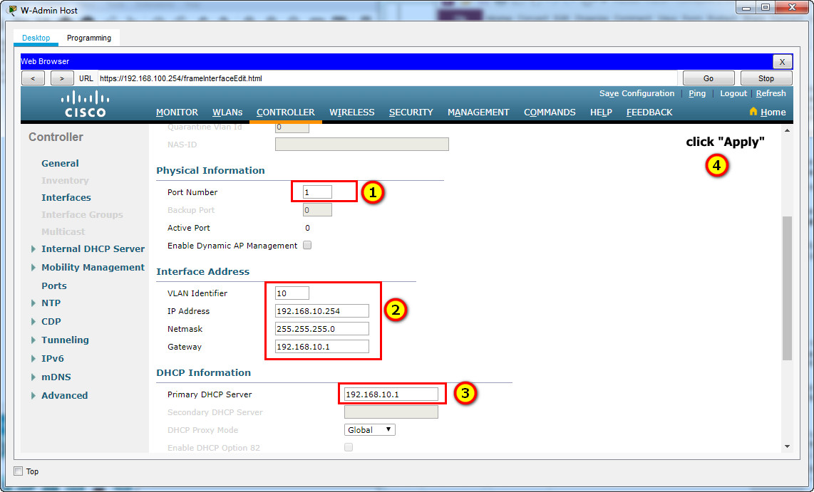
b. Use the information in the addressing table to configure the addressing settings for the interface. The interface will be using a DHCP pool that is configured on the subinterface that is assigned to VLAN 10 on router Branch-101.
VLAN Identifier: 10
IP Address: 192.168.10.254
Netmask: 255.255.255.0
Gateway: 192.168.10.1
Primary DHCP Server: 192.168.10.1
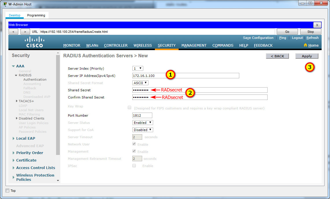
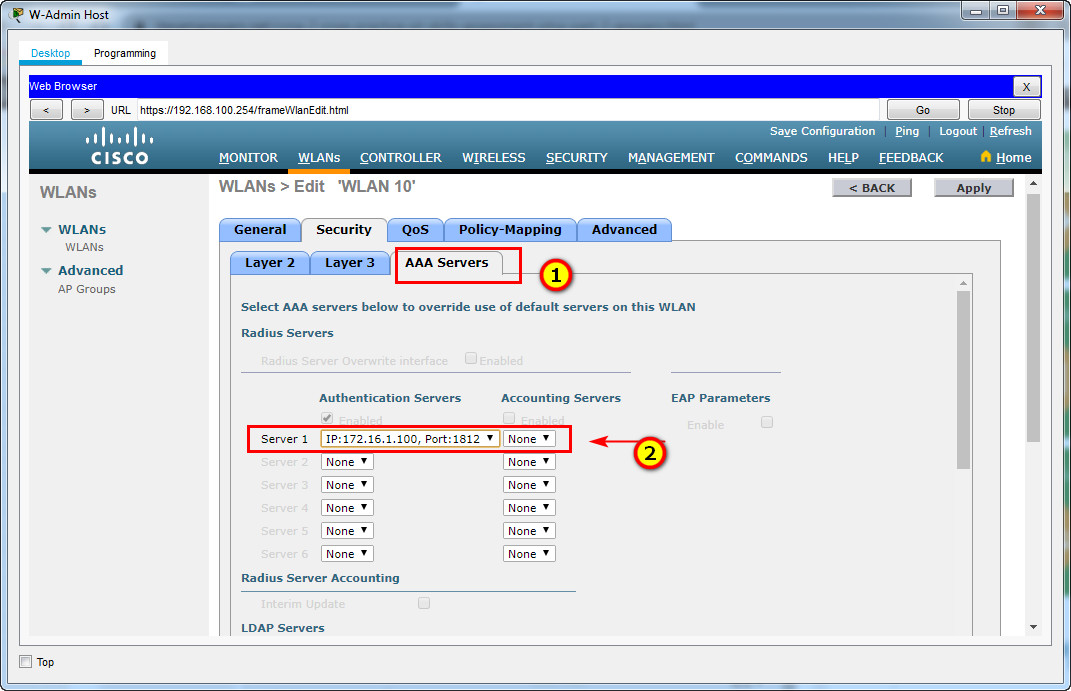
Step 2: Configure a RADIUS server.
a. Configure the WLC with the RADIUS server IPv4 address.
b. Use a shared secret of RADsecret.
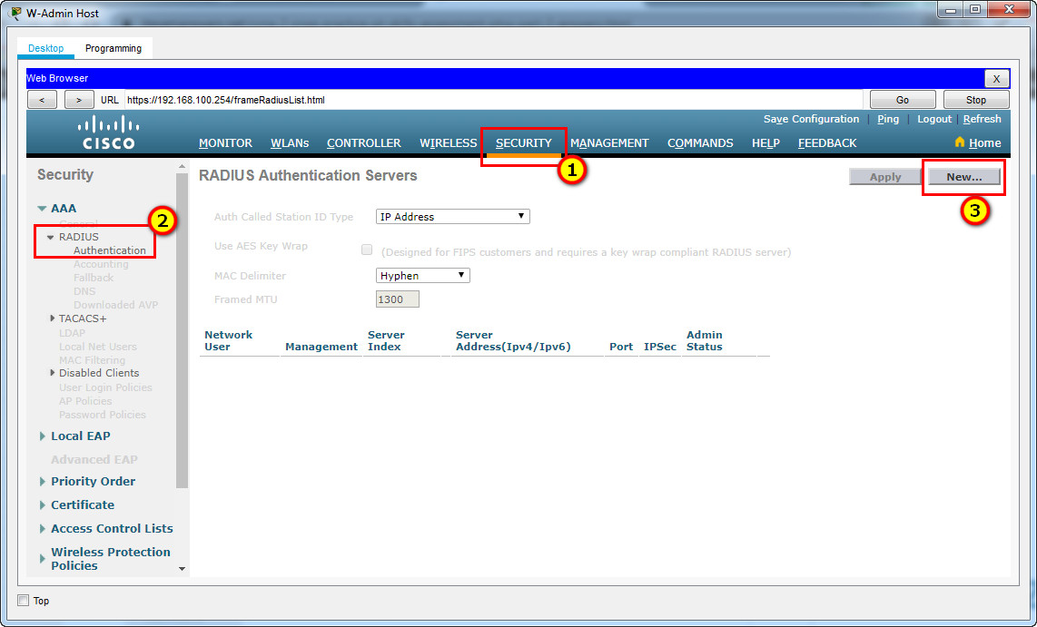
Server IP Address: 172.16.1.100
Shared Secret: RADsecret
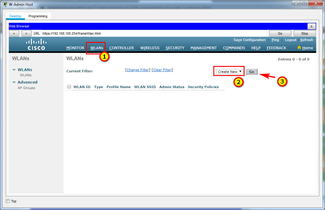
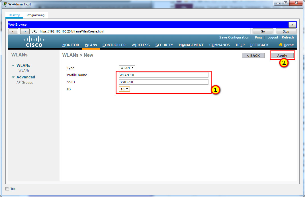
Step 3: Configure a Wireless LAN.
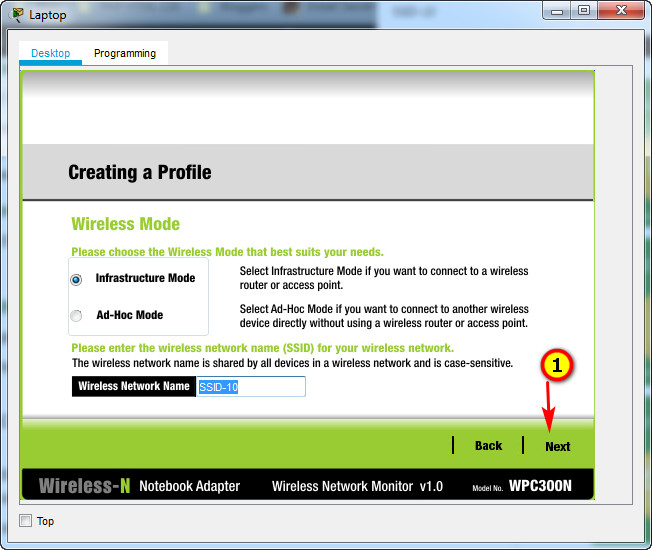
a. Create a new WLAN. Name it WLAN 10 and configure the SSID as SSID-10.
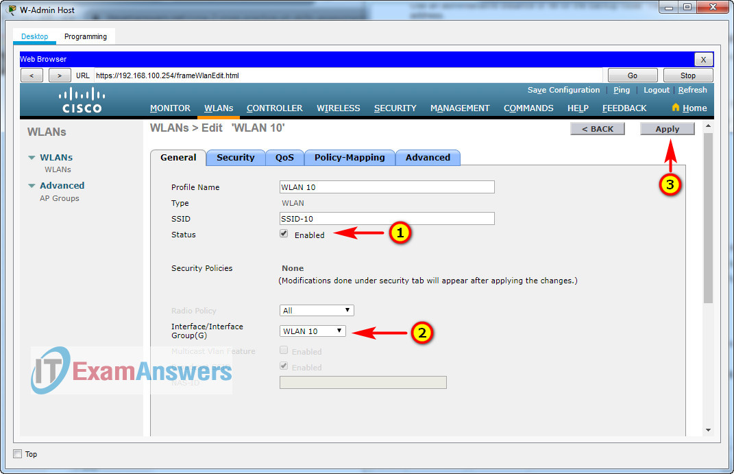
b. The wireless LAN should use the VLAN interface that was previously configured.
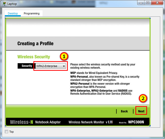
c. Configure the WLAN to use the WPA2 security policy and dot1x Authentication Key Management.
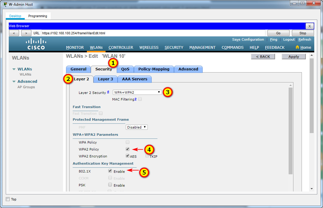
d. Configure the WLAN to use the RADIUS server that was previously configured to authenticate wireless users.
e. Open the Advanced tab and scroll down to the Flexconnect sections. Activate FlexConnect Local Switching and FlexConnect Local Auth.
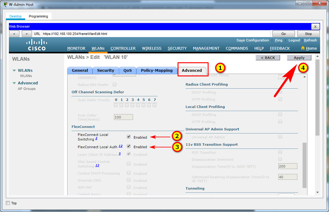
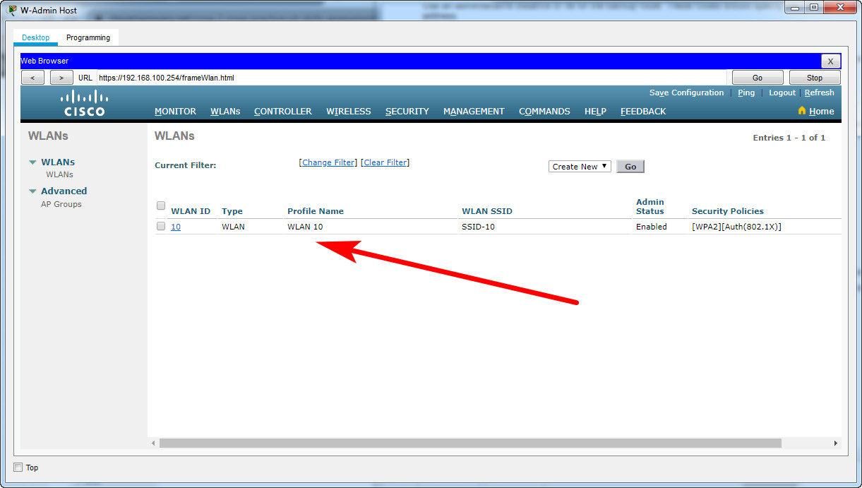
f. Verify that the WLAN is configured and operational.
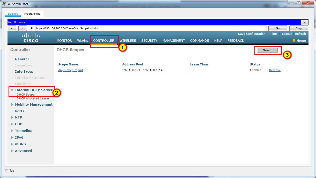
Step 4: Configure a DHCP scope for the management network.
Configure a new DHCP scope to be used by the LAPs and other management devices on the network.
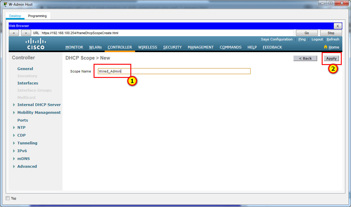
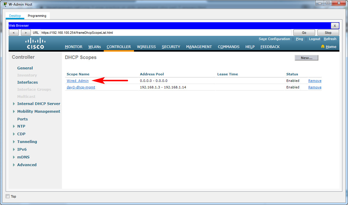
a. Name the DHCP scope Wired_Admin.
b. Start the scope at address 192.168.100.240. End the scope at address 192.168.100.249.
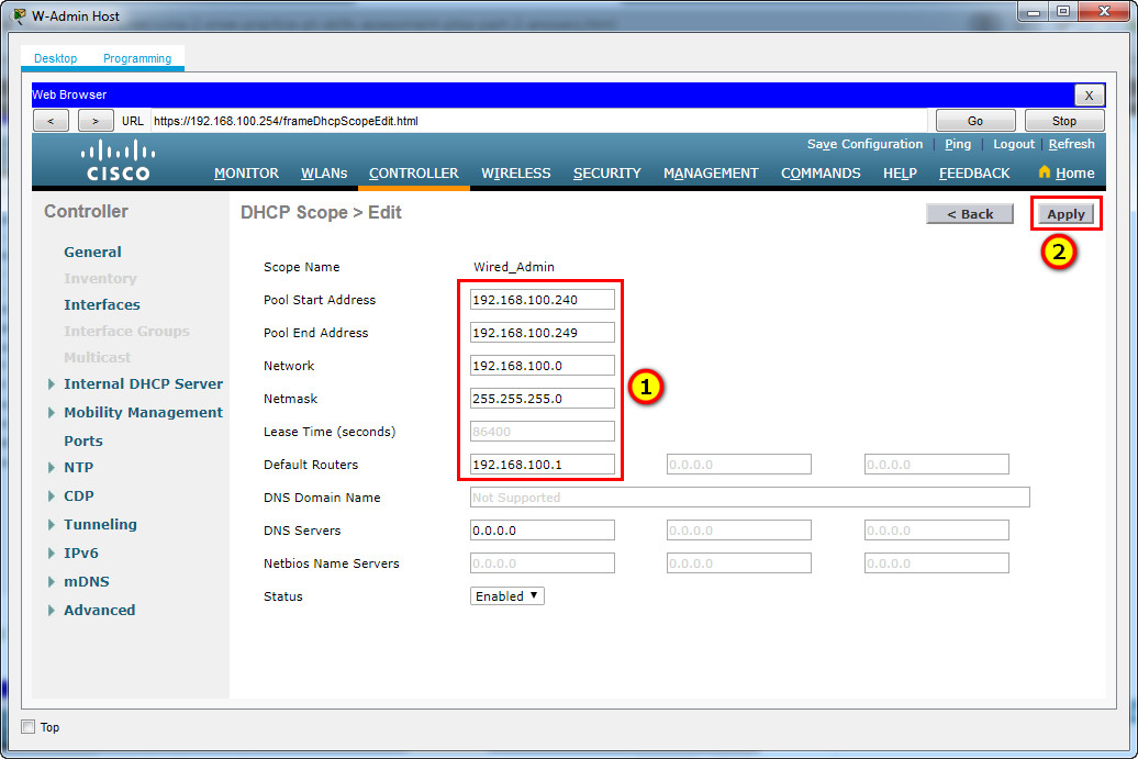
Pool End Address: 192.168.100.249
Network: 192.168.100.0
Netmask: 255.255.255.0
Default Routers: 192.168.100.1
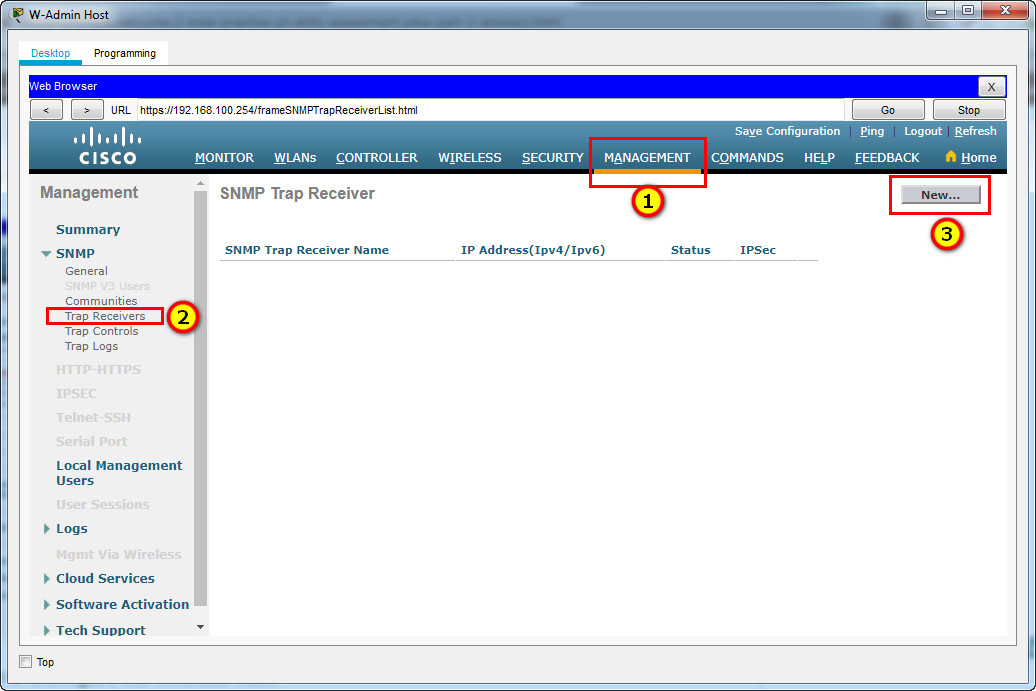
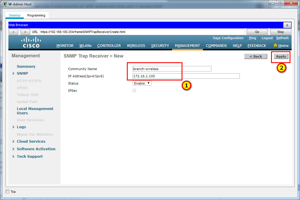
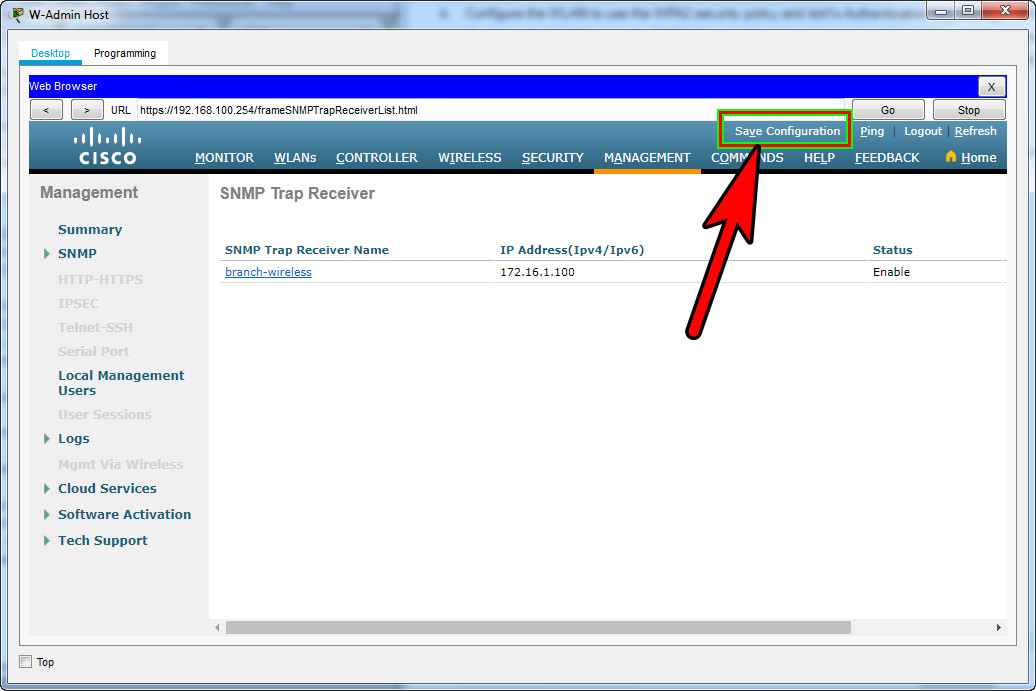
Step 5: Configure an SNMP server.
Configure an SNMP server to receive traps from the WLC.
a. Use the community name branch-wireless.
b. Use 172.16.1.100 as the server address.
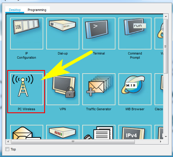
Step 6: Configure the wireless host.
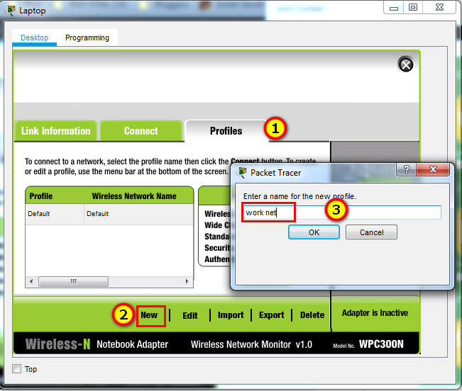
Configure the Laptop (or Wireless Host) to connect to the WLAN.
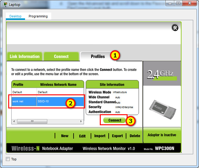
a. Create a new wireless profile on the host. Use the name work net for the profile.
Click Wireless Host Laptop and open the PC Wireless app
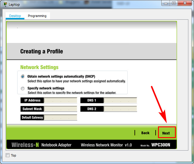
b. Configure the profile for the SSID of the WLAN.
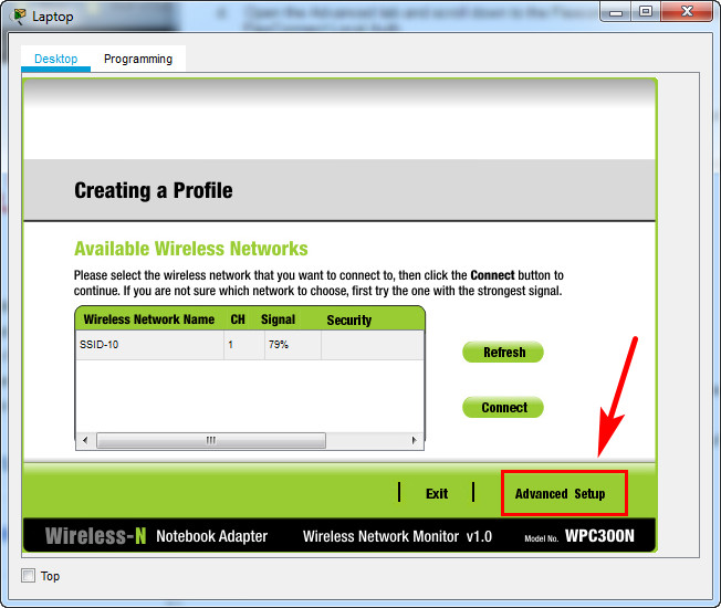
c. Use enterprise authentication with a username of user1 and password of user1Pass.
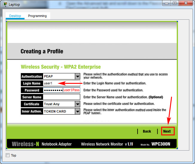

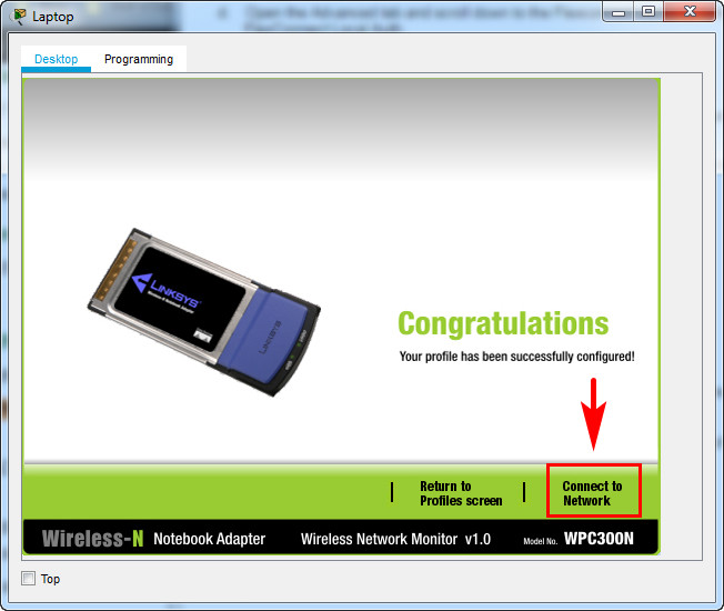
d. When you are finished, click Connect to Network. It will take time for the connection to be established.
Result
You can click the Fast Forward Time button speed up the process.
Fast script – Answers
Part 1 + 2 + 3
S1-1 Switch or (SW-1 Switch)
en
config t
vlan 10
name users
vlan 999
name unused
exit

interface range f0/1-5, g0/1
switchport mode access
switchport access vlan 10

interface range f0/1-5
switchport port-security
switchport port-security maximum 4
switchport port-security violation restrict
switchport port-security aging time 10
switchport port-security mac-address sticky
exit

interface f0/1
switchport port-security mac-address 00D0.D3DC.2825
exit

ip dhcp snooping
ip dhcp snooping vlan 10,999
interface range f0/1-5, g0/1
ip dhcp snooping limit rate 5
exit
interface g0/1
ip dhcp snooping trust
exit

ip arp inspection vlan 10,999
interface g0/1
ip arp inspection trust
exit

interface range f0/1-5
spanning-tree portfast
spanning-tree bpduguard enable

interface range f0/6-24, g0/2
switchport mode access
switchport access vlan 999
shutdown
Branch-101 Router or (RTR-Branch Router)
en
config t
interface g0/0/0.10
description WLAN users
encapsulation dot1q 10
ip address 192.168.10.1 255.255.255.0
exit

ip dhcp excluded-address 192.168.10.1
ip dhcp excluded-address 192.168.10.254
ip dhcp pool WLAN-hosts
network 192.168.10.0 255.255.255.0
default-router 192.168.10.1
dns-server 198.51.100.163
exit

interface g0/0/1
ip address dhcp

end
exit
Central Router or (RTR-HQ Router)
enable
conf t
ip route 0.0.0.0 0.0.0.0 g0/0/2
ip route 0.0.0.0 0.0.0.0 s0/1/0 10
ip route 192.168.10.0 255.255.255.0 g0/0/2
ip route 192.168.10.0 255.255.255.0 s0/1/0 10
ip route 192.168.3.122 255.255.255.255 s0/1/1
ipv6 unicast-routing
ipv6 route ::/0 2001:DB8:ACAD:A::2
ipv6 route ::/0 2001:db8:acad:b::2 10
ipv6 route 2001:db8:acad:3::122/128 2001:db8:acad:d::2
Branch-101 Router or (RTR-Branch Router)
enable
configure terminal
ip route 0.0.0.0 0.0.0.0 g0/0/1
ip route 0.0.0.0 0.0.0.0 s0/1/0 10
ipv6 unicast-routing
ipv6 route ::/0 2001:DB8:ACAD:C::1
ipv6 route ::/0 2001:DB8:ACAD:B::1 10