Última actualización: septiembre 27, 2021
CCNAv7 Enterprise Networking, Security, and Automation v7.0 (ENSA)
ENSA Practice PT Skills Assessment (PTSA)
Update May-2021 – 100% Scored
A few things to keep in mind while completing this activity:
- Do not use the browser Back button or close or reload any exam windows during the exam.
- Do not close Packet Tracer when you are done. It will close automatically.
- Click the Submit Assessment button in the browser window to submit your work.
Topology
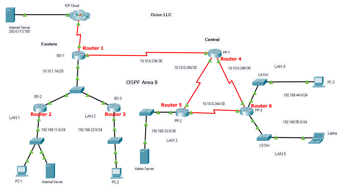
Addressing Table
| Device Name | G0/0/0 | 10.10.1.17/29 |
|---|---|---|
| BD-1 | G0/0/0 | 10.10.1.17/29 |
| S0/1/0 | 10.10.0.237/30 | |
| S0/1/1 | 192.0.2.113/29 | |
| BD-2 | G0/0/0 | 192.168.11.1/24 |
| G0/0/1 | 10.10.1.18/29 | |
| BD-3 | G0/0/0 | 192.168.22.1/24 |
| G0/0/1 | 10.10.1.19/29 | |
| PP-1 | G0/0/0 | 192.168.66.1/30 |
| S0/1/0 | 10.10.0.249/30 | |
| S0/1/1 | 10.10.0.241/30 | |
| S0/2/0 | 10.10.0.238/30 | |
| PP-2 | G0/0/0 | 192.168.33.1/28 |
| S0/1/0 | 10.10.0.245/30 | |
| S0/1/1 | 10.10.0.242/30 | |
| PP-3 | G0/0/0 | 192.168.44.1/24 |
| G0/0/1 | 192.168.55.1/24 | |
| S0/1/0 | 10.10.0.250/30 | |
| S0/1/1 | 10.10.0.246/30 | |
| PC-1 | NIC | 192.168.11.11/24 |
| PC-2 | NIC | 192.168.22.22/24 |
| PC-3 | NIC | 192.168.44.44/24 |
| Admin Server | NIC | 192.168.33.14/28 |
| Internal Server | NIC | 192.168.11.100 |
| Laptop | NIC | 192.168.55.55/24 |
| Internet Server | NIC | 203.0.113.100 |
Introduction
You are completing the configuration of the Ocisc LLC network.
You are not required to configure host addressing.
You will practice and be assessed on the following skills:
- Configuration of OSPFv2 routing
- Customization of OSPF.
- Configuration of static NAT.
- Configuration of dynamic NAT with PAT.
- Configuration of various types of ACLs.
- Configuration of a router with NTP as a system time source.
- Backing up an IOS image to a TFTP server.
Instructions
Part 1: Configure OSPF
Step 1: Activate OSPF.
Use process ID 10 for OSPF activation on all routers.
a. Activate OSPF by configuring the interfaces of the network devices in the Eastern network, where required.
b. Activate OSPF using network statements and inverse masks on the routers in the Central Network network.
Note: For the purposes of this assessment, please enter the network statements in the following order:
1) On Router 4 (PP-1)
- the Serial0/1/1 network
- the Serial0/2/0 network
- the Serial0/1/0 network
2) On Router 5 (PP-2)
- the Serial0/1/1 network
- the Serial0/1/0 network
- the GigabitEthernet0/0/0 network
3) On Router 6 (PP-3)
- the Serial0/1/0 network
- the Serial0/1/1 network
- the GigabitEthernet0/0/0 network
- the GigabitEthernet0/0/1 network
Step 2: Configure router IDs.
Configure router IDs on the multiaccess network routers as follows:
- BD-1: 9.9.9.9
- BD-2: 8.8.8.8
- BD-3: 7.7.7.7
Step 3: Customize OSPF operation.
- a. Configure router BD-1 with the highest OSPF interface priority so that it will always be the designated router of the multiaccess network.
- b. On router BD-1, configure a default route to the ISP cloud using the exit interface command argument.
- c. Automatically distribute the default route to all routers in the network.
- d. Configure the hello and dead timer values on the interfaces that connect BD-1 and PP-1 to be twice the default values.
- e. Configure the OSPF routers so that the default cost value for all Gigabit Ethernet interfaces will be 10 and the cost value for Fast Ethernet will be 100.
- f. Configure the OSPF cost value of PP-1 interface Serial0/1/1 to 50.
- g. Configure OSPF so that routing updates are not sent into networks where OSPF updates are not required.
Part 2: Configure NAT
In this part of the practice skills assessment, you will configure static and dynamic NAT at the network edge.
Step 1: Configure static NAT
Configure static NAT to translate the address of the Internal Server on LAN-1 to the public address of 192.0.2.115. Verify that the translations are occurring.
Step 2: Configure dynamic PAT.
a. Create access list 1 to allow all addresses in the 192.168.0.0/16 network to be translated.
b. Create a NAT pool named POOL-1. It should use address in the range 192.0.2.116 -192.0.2.118.
c. Configure NAT to dynamically use the addresses in the pool for all traffic entering and exiting the company network. Remember that it is likely that more than three hosts will be accessing traffic on the Internet.
Part 3: Configure ACLs
Configure access control lists to meet the following requirements.
Note: Use host and any keywords whenever possible. Always explicitly configure the default deny condition when it is to be used as part of the ACL functionality so that it can be logged when the condition is met. You do not need to specify the default deny condition if it is counteracted with permit ip any any for this assessment. All ACLs should be placed in the most efficient location possible according to the guidelines specified in the curriculum.
a. Create a named standard access list to explicitly prevent all external traffic accessing the telnet lines on RTR-1. Name the list VTY-BLOCK. All addresses on the 192.168.0.0/16 network only should be allowed to access the VTY lines. Verify that the list works as specified.
b. Create a numbered standard ACL to prevent all hosts on LAN 1 from accessing LAN 2. Use 10 as the number for the list.
c. Create an extended numbered ACL that will prevent traffic from the LAN 4 network from accessing the HTTP service that is running on Admin Server. All other traffic from LAN 4 hosts should be able to access the network. Number the list 101.
Part 4: Manage Network Devices
Step 1: Configure NTP
Configure router PP-2 to use Admin Server as its time source.
Step 2: Backup IOS to Server
Backup the IOS image file on router PP-2 to Admin Server.
Answers Script:
Router 1 possible names: BD-1; RTR-1; RTR-A
enable
configure ter
router ospf 10
exit

interface g0/0/0
ip ospf 10 area 0
interface s0/1/0
ip ospf 10 area 0
exit

router ospf 10
router-id 9.9.9.9
exit

int g0/0/0
ip ospf priority 255
exit
ip route 0.0.0.0 0.0.0.0 s0/1/1
router ospf 10
default-information originate
exit

int s0/1/0
ip ospf hello-interval 20
ip ospf dead-interval 80
exit

router ospf 10
auto-cost reference-bandwidth 10000
exit

router ospf 10
passive-interface s0/1/1
exit

ip nat inside source static 192.168.11.100 192.0.2.115
int s0/1/1
ip nat outside
int g0/0/0
ip nat inside
exit

access-list 1 permit 192.168.0.0 0.0.255.255
ip nat pool POOL-1 192.0.2.116 192.0.2.118 netmask 255.255.255.248
ip nat inside source list 1 pool POOL-1 overload
int s0/1/0
ip nat inside
exit

ip access-list standard VTY-BLOCK
permit 192.168.0.0 0.0.255.255
deny any
exit
line vty 0 4
access-class VTY-BLOCK in
exit

end
copy running-config startup-config
Router 2 possible names: BD-2; RTR-2; RTR-B
enable
configure terminal
router ospf 10
exit

interface g0/0/0
ip ospf 10 area 0
interface g0/0/1
ip ospf 10 area 0
exit

router ospf 10
router-id 8.8.8.8
exit

router ospf 10
auto-cost reference-bandwidth 10000
exit

router ospf 10
passive-interface g0/0/0
exit

end
copy running-config startup-config
Router 3 possible names: BD-3; RTR-3; RTR-C
enable
configure terminal
router ospf 10
exit

interface g0/0/0
ip ospf 10 area 0
interface g0/0/1
ip ospf 10 area 0
exit

router ospf 10
router-id 7.7.7.7
exit

router ospf 10
auto-cost reference-bandwidth 10000
exit

router ospf 10
passive-interface g0/0/0
exit

access-list 10 deny 192.168.11.0 0.0.0.255
access-list 10 permit any
int g0/0/1
ip access-group 10 in
exit

end
copy running-config startup-config
Router 4 possible names: PP-1; RTR-4; RTR-D
enable
configure terminal
router ospf 10
network 10.10.0.240 0.0.0.3 area 0
network 10.10.0.236 0.0.0.3 area 0
network 10.10.0.248 0.0.0.3 area 0
exit

int s0/2/0
ip ospf hello-interval 20
ip ospf dead-interval 80
exit

router ospf 10
auto-cost reference-bandwidth 10000
exit

int s0/1/1
ip ospf cost 50
exit

router ospf 10
passive-interface g0/0/0
exit

end
copy running-config startup-config
Router 5 possible names: PP-2; RTR-5; RTR-E
enable
configure terminal
router ospf 10
network 10.10.0.240 0.0.0.3 area 0
network 10.10.0.244 0.0.0.3 area 0
network 192.168.33.0 0.0.0.15 area 0
exit

router ospf 10
auto-cost reference-bandwidth 10000
exit

router ospf 10
passive-interface g0/0/0
exit

ntp server 192.168.33.14
exit

copy running-config startup-config
Router 6 possible names: PP-3; RTR-6; RTR-F
enable
configure terminal
router ospf 10
network 10.10.0.248 0.0.0.3 area 0
network 10.10.0.244 0.0.0.3 area 0
network 192.168.44.0 0.0.0.255 area 0
network 192.168.55.0 0.0.0.255 area 0
exit

router ospf 10
auto-cost reference-bandwidth 10000
exit

router ospf 10
passive-interface g0/0/0
passive-interface g0/0/1
exit

access-list 101 deny tcp any host 192.168.33.14 eq www
access-list 101 permit ip any any
int g0/0/0
ip access-group 101 in

end
copy running-config startup-config
Part 4, step 2 (Router 5 possible names: PP-2; RTR-5; RTR-E)
Note: IOS image file (.bin file) name may be different
PP-2>enable
PP-2#show flash:

System flash directory:
File  Length   Name/status
  3   486899872isr4300-universalk9.03.16.05.S.155-3.S5-ext.SPA.bin
  2   28282    sigdef-category.xml
  1   227537   sigdef-default.xml
[487155691 bytes used, 2761893909 available, 3249049600 total]
3.17338e+06K bytes of processor board System flash (Read/Write)

PP-2#copy flash tftp
Source filename []? isr4300-universalk9.03.16.05.S.155-3.S5-ext.SPA.bin
Address or name of remote host []? 192.168.33.14
Destination filename [isr4300-universalk9.03.16.05.S.155-3.S5-ext.SPA.bin]? [Press Enter]