Última actualización: septiembre 12, 2022
3.3.1.2 Packet Tracer: desafío de integración de habilidades (versión para el instructor)
Nota para el instructor: el color de fuente rojo o las partes resaltadas en gris indican texto que aparece en la copia del instructor solamente.
Topología
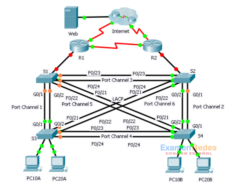
Tabla de asignación de direcciones
| Dispositivo | Interfaz | Dirección IP | Máscara de subred | Gateway predeterminado | Asociación de VLAN |
|---|---|---|---|---|---|
| R1 | G0/0.1 | 192.168.99.1 | 255.255.255.0 | N/A | VLAN 99 |
| G0/0.10 | 192.168.10.1 | 255.255.255.0 | N/A | VLAN 10 | |
| G0/0.20 | 192.168.20.1 | 255.255.255.0 | N/A | VLAN 20 | |
| S0/0/0 | 209.165.22.222 | 255.255.255.224 | N/A | N/A | |
| S0/0/1 | 192.168.1.1 | 255.255.255.0 | N/A | N/A | |
| R2 | G0/0.1 | 192.168.99.2 | 255.255.255.0 | N/A | VLAN 99 |
| G0/0.10 | 192.168.10.2 | 255.255.255.0 | N/A | VLAN 10 | |
| G0/0.20 | 192.168.20.2 | 255.255.255.0 | N/A | VLAN 20 | |
| S0/0/0 | 192.168.1.2 | 255.255.255.0 | N/A | N/A | |
| S0/0/1 | 209.165.22.190 | 255.255.255.224 | N/A | N/A | |
| ISP | S0/0/0 | 209.165.22.193 | 255.255.255.224 | N/A | N/A |
| S0/0/1 | 209.165.22.161 | 255.255.255.224 | N/A | N/A | |
| Web | NIC | 64.104.13.130 | 255.255.255.252 | 64.104.13.129 | N/A |
| PC10A | NIC | 192.168.10.101 | 255.255.255.0 | 192.168.10.1 | VLAN 10 |
| PC10B | NIC | 192.168.10.102 | 255.255.255.0 | 192.168.10.1 | VLAN 10 |
| PC20A | NIC | 192.168.20.101 | 255.255.255.0 | 192.168.20.1 | VLAN 20 |
| PC20B | NIC | 192.168.20.102 | 255.255.255.0 | 192.168.20.1 | VLAN 20 |
Situación
En esta actividad, hay dos routers configurados para comunicarse entre sí. Usted es responsable de configurar las subinterfaces para que se comuniquen con los switches. Configurará redes VLAN, enlaces troncales y EtherChannel con PVST. Todos los dispositivos de Internet se configuraron previamente.
Requisitos
Usted es responsable de configurar los routers R1 y R2, y los switches S1, S2, S3 y S4.
Nota: Packet Tracer no permite asignar valores de punto inferiores a 1. Dado que esta actividad evalúa 154 elementos, no se asigna un valor de punto a todas las configuraciones. Haga clic en Check Results (Verificar resultados) > Assessment Items (Elementos de evaluación) para verificar que haya configurado correctamente los 154 elementos.
Routing entre VLAN
En el R1 y el R2, habilite y configure las subinterfaces con el siguiente requisito:
– Configure la encapsulación dot1q apropiada.
– configurar VLAN 99 como VLAN nativa.
– Configure la dirección IP de la subinterfaz según la tabla de direccionamiento.
Routing
Configure OSPFv2 con los siguientes requisitos:
– Utilice la ID de proceso 1.
– Anuncie la red para cada subinterfaz.
– Deshabilite las actualizaciones OSPF para cada subinterfaz.
VLAN
• Para todos los switches, cree las VLAN 10, 20 y 99.
• Configure los siguientes puertos estáticos para el S1 y el S2:
– F0/1 a 9 como puertos de acceso en la VLAN 10.
– F0/10 a 19 como puertos de acceso en la VLAN 20.
– F0/20 a F24 y G0/1 a 0/2 como enlace troncal nativo para la VLAN 99.
• Configure los siguientes puertos estáticos para el S3 y S4:
– F0/1 a 9 como puertos de acceso en la VLAN 10.
– F0/10 a 20 como puertos de acceso en la VLAN 20.
– F0/21 a F24 y G0/1 a 0/2 como enlace troncal nativo para la VLAN 99.
EtherChannels
• Todos los EtherChannels se configuran como LACP.
• Todos los EtherChannels se configuran de forma estática como enlace troncal nativo para la VLAN 99.
• Utilice la siguiente tabla para configurar los puertos de switch apropiados para formar EtherChannels:
| Canal de puertos | Dispositivo: puertos | Dispositivo: puertos |
|---|---|---|
| 1 | S1: G0/1 – 2 | S3: G0/1 – 2 |
| 2 | S2: G0/1 – 2 | S4: G0/1 – 2 |
| 3 | S1: F0/23 – 24 | S2: F0/23 – 24 |
| 4 | S3: F0/23 – 24 | S4: F0/23 – 24 |
| 5 | S1: F0/21 – 22 | S4: F0/21 – 22 |
| 6 | S2: F0/21 – 22 | S3: F0/21 – 22 |
Árbol de expansión
• Configure el modo de árbol de expansión rápido por VLAN para todos los switches.
• Configure las prioridades del árbol de expansión según la siguiente tabla:
| Dispositivo | Prioridad de VLAN 10 | Prioridad de VLAN 20 |
|---|---|---|
| S1 | 4096 | 8192 |
| S2 | 8192 | 4096 |
| S3 | 32768 | 32768 |
| S4 | 32768 | 32768 |
Nota para el instructor: Packet Tracer 6.0.1 no califica el comando switchport mode trunk ni el comando switchport trunk native vlan en las interfaces de canal de puertos.
Conectividad
• Todas las computadoras deben poder hacer ping a Web y a las otras computadoras.
Respuestas
Router R1
!R1
enable
configure t
interface GigabitEthernet0/0
no shut
!
interface GigabitEthernet0/0.1
encapsulation dot1Q 99 native
ip address 192.168.99.1 255.255.255.0
!
interface GigabitEthernet0/0.10
encapsulation dot1Q 10
ip address 192.168.10.1 255.255.255.0
!
interface GigabitEthernet0/0.20
encapsulation dot1Q 20
ip address 192.168.20.1 255.255.255.0
!
router ospf 1
passive-interface GigabitEthernet0/0.1
passive-interface GigabitEthernet0/0.10
passive-interface GigabitEthernet0/0.20
network 192.168.99.0 0.0.0.255 area 0
network 192.168.10.0 0.0.0.255 area 0
network 192.168.20.0 0.0.0.255 area 0
end
copy run start
R2 del router
!R2
enable
configure t
!
interface GigabitEthernet0/0
no shut
!
interface GigabitEthernet0/0.1
encapsulation dot1Q 99 native
ip address 192.168.99.2 255.255.255.0
!
interface GigabitEthernet0/0.10
encapsulation dot1Q 10
ip address 192.168.10.2 255.255.255.0
!
interface GigabitEthernet0/0.20
encapsulation dot1Q 20
ip address 192.168.20.2 255.255.255.0
!
router ospf 1
passive-interface GigabitEthernet0/0.1
passive-interface GigabitEthernet0/0.10
passive-interface GigabitEthernet0/0.20
network 192.168.99.0 0.0.0.255 area 0
network 192.168.10.0 0.0.0.255 area 0
network 192.168.20.0 0.0.0.255 area 0
end
copy run start
Switch S1
!S1
enable
configure t
vlan 10
vlan 20
vlan 99
interface range f0/1 - 9
switchport mode access
switchport access vlan 10
inte range f0/10 - 19
switchport mode access
switchport access vlan 20
interface range f0/20 - 24, g0/1-2
switchport mode trunk
switchport trunk native vlan 99
!
interface range g0/1 - 2
channel-group 1 mode active
interface range f0/21 - 22
channel-group 5 mode active
interface range f0/23 - 24
channel-group 3 mode active
!
interface po 1
switchport mode trunk
switchport trunk native vlan 99
interface po 3
switchport mode trunk
switchport trunk native vlan 99
interface po 5
switchport mode trunk
switchport trunk native vlan 99
!
spanning-tree mode rapid-pvst
spanning-tree vlan 10 priority 4096
spanning-tree vlan 20 priority 8192
end
copy run start
Switch S2
!S2
enable
configure t
vlan 10
vlan 20
vlan 99
interface range f0/1 - 9
switchport mode access
switchport access vlan 10
inte range f0/10 - 19
switchport mode access
switchport access vlan 20
inte range f0/20 - 24, g0/1-2
switchport mode trunk
switchport trunk native vlan 99
!
interface range g0/1 - 2
channel-group 2 mode active
interface range f0/21 - 22
channel-group 6 mode active
interface range f0/23 - 24
channel-group 3 mode active
!
interface po 2
switchport mode trunk
switchport trunk native vlan 99
interface po 3
switchport mode trunk
switchport trunk native vlan 99
interface po 6
switchport mode trunk
switchport trunk native vlan 99
!
spanning-tree mode rapid-pvst
spanning-tree vlan 10 priority 8192
spanning-tree vlan 20 priority 4096
end
copy run start
Switch S3
!S3
enable
configure t
vlan 10
vlan 20
vlan 99
interface range f0/1 - 9
switchport mode access
switchport access vlan 10
inte range f0/10 - 20
switchport mode access
switchport access vlan 20
inte range f0/21 - 24, g0/1-2
switchport mode trunk
switchport trunk native vlan 99
!
interface range g0/1 - 2
channel-group 1 mode active
interface range f0/21 - 22
channel-group 6 mode active
interface range f0/23 - 24
channel-group 4 mode active
!
interface po 1
switchport mode trunk
switchport trunk native vlan 99
interface po 4
switchport mode trunk
switchport trunk native vlan 99
interface po 6
switchport mode trunk
switchport trunk native vlan 99
!
spanning-tree mode rapid-pvst
spanning-tree vlan 10 priority 32768
spanning-tree vlan 20 priority 32768
end
copy run start
Switch S4
!S4
enable
configure t
vlan 10
vlan 20
vlan 99
interface range f0/1 - 9
switchport mode access
switchport access vlan 10
inte range f0/10 - 20
switchport mode access
switchport access vlan 20
inte range f0/21 - 24, g0/1-2
switchport mode trunk
switchport trunk native vlan 99
!
interface range g0/1 - 2
channel-group 2 mode active
interface range f0/21 - 22
channel-group 5 mode active
interface range f0/23 - 24
channel-group 4 mode active
interface po 2
switchport mode trunk
switchport trunk native vlan 99
interface po 4
switchport mode trunk
switchport trunk native vlan 99
interface po 5
switchport mode trunk
switchport trunk native vlan 99
!
spanning-tree mode rapid-pvst
spanning-tree vlan 10 priority 32768
spanning-tree vlan 20 priority 32768
end
copy run start
