Última actualización: septiembre 14, 2022
8.1.1.8 Packet Tracer: Desafío de solución de problemas – Documentar la red (Versión para el instructor)
Nota para el instructor: El color de fuente rojo o las partes resaltadas en gris indican texto que aparece en la copia del instructor solamente.
Topología
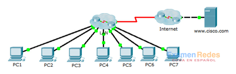
Tabla de asignación de direcciones
| Dispositivo | Interfaz | Dirección IP | Máscara de subred | Gateway predeterminado |
|---|---|---|---|---|
| PC1 | NIC | 10.2.15.10 | 255.255.255.0 | 10.2.15.1 |
| PC2 | NIC | 10.2.25.10 | 255.255.255.0 | 10.2.25.1 |
| PC3 | NIC | 10.2.35.10 | 255.255.255.0 | 10.2.35.1 |
| PC4 | NIC | 10.3.100.4 | 255.255.255.0 | 10.3.100.1 |
| PC5 | NIC | 10.3.100.5 | 255.255.255.0 | 10.3.100.1 |
| PC6 | NIC | 10.4.1.10 | 255.255.255.0 | 10.4.1.1 |
| PC7 | NIC | 10.5.1.10 | 255.255.255.0 | 10.5.1.1 |
| Servidor DNS | NIC | 10.1.100.2 | 255.255.255.0 | 10.1.100.1 |
| R1 | S0/0/0 | 10.1.0.4 | 255.255.255.248 | N/A |
| R1 | G0/0 | 10.4.1.1 | 255.255.255.0 | N/D |
| R2 | S0/0/0 | 10.1.0.3 | 255.255.255.248 | N/A |
| R2 | G0/0,100 | 10.3.100.1 | 255.255.255.0 | N/D |
| R2 | G0/0,105 | 10.3.105.1 | 255.255.255.0 | N/D |
| R3 | S0/0/0 | 10.1.0.2 | 255.255.255.248 | N/A |
| R3 | G0/0,5 | 10.2.5.1 | 255.255.255.0 | N/D |
| R3 | G0/0,15 | 10.2.15.1 | 255.255.255.0 | N/D |
| R3 | G0/0,25 | 10.2.25.1 | 255.255.255.0 | N/D |
| R3 | G0/0,35 | 10.2.35.1 | 255.255.255.0 | N/D |
| R4 | S0/0/0 | 10.1.0.5 | 255.255.255.248 | N/A |
| R4 | G0/0 | 10.5.1.1 | 255.255.255.0 | N/D |
| R5 | S0/0/0 | 10.1.0.1 | 255.255.255.248 | N/A |
| R5 | S0/0/1 | 209.165.201.2 | 255.255.255.252 | N/D |
| R5 | G0/0 | 10.1.100.1 | 255.255.255.0 | N/D |
| S1 | Ninguna | Ninguna | Ninguna | Ninguna |
| S2 | VLAN 105 | 10.3.105.21 | 255.255.255.0 | 10.3.105.1 |
| S3 | VLAN 105 | 10.3.105.22 | 255.255.255.0 | 10.3.105.1 |
| S4 | VLAN 5 | 10.2.5.21 | 255.255.255.0 | 10.2.5.1 |
| S5 | VLAN 5 | 10.2.5.23 | 255.255.255.0 | 10.2.5.1 |
| S6 | VLAN 5 | 10.2.5.22 | 255.255.255.0 | 10.2.5.1 |
| S7 | Ninguna | Ninguna | Ninguna | Ninguna |
Objetivos
Parte 1: Probar la conectividad
Parte 2: Detectar la información de configuración de PC
Parte 3: Detectar la información de configuración del gateway predeterminado
Parte 4: Detectar rutas y vecinos en la red
Parte 5: Dibujar la topología de red
Aspectos básicos/situación
En esta actividad, se abarcan los pasos que se deben seguir para detectar una red principalmente mediante el uso de los comandos telnet, show cdp neighbors detail y show ip route. Esta es la parte 1 de una actividad que consta de dos partes. La parte 2 es Packet Tracer: Desafío de resolución de problemas sobre el uso del registro para resolver problemas.
La topología que ve cuando abre la actividad de Packet Tracer no muestra todos los detalles de la red. Los detalles se ocultaron mediante la función de clúster de Packet Tracer. La infraestructura de la red se contrajo, y la topología en el archivo muestra solo las terminales. Su tarea consiste en usar sus conocimientos sobre comandos de detección y redes para obtener información acerca de la topología de la red completa y registrarla.
Probar la conectividad
Packet Tracer necesita algo de tiempo para que la red logre la convergencia. Emita un comando ping entre las PC y el nuevo servidor www.cisco.com para verificar la convergencia y probar la red. Todas las PC deberían poder enviar comandos ping entre ellas, además de al servidor. Recuerde que puede llevar varios comandos ping antes de lograr un resultado correcto.
Detectar la información de configuración de la computadora
Paso 1: Acceder al símbolo del sistema de la PC1.
Haga clic en PC1, en la ficha Desktop (Escritorio) y, luego, en Command Prompt (Línea de comandos).
Paso 2: Determinar la información de direccionamiento de la PC1.
Para determinar la configuración de asignación de direcciones IP actual, introduzca el comando ipconfig /all.
Nota: En Packet Tracer, debe introducir un espacio entre ipconfig y /all.
Paso 3: Registrar la información de la PC1 en la tabla de direccionamiento.
PC> ipconfig /all

FastEthernet0 Connection:(default port)
Physical Address................: 0001.97DA.E057
Link-local IPv6 Address.........: FE80::201:97FF:FEDA:E057
IP Address......................: 10.2.15.10
Subnet Mask.....................: 255.255.255.0
Default Gateway.................: 10.2.15.1
DNS Servers.....................: 10.1.100.2
DHCP Servers....................: 0.0.0.0
Paso 4: Repetir los pasos 1 a 3 en las PC 2 a 7.
Detectar la información de configuración del gateway predeterminado
Paso 1: Probar la conectividad entre la PC1 y su gateway predeterminado.
Desde PC1, emita un comando ping al gateway predeterminado para asegurarse de que tenga conectividad.
Paso 2: Acceder al gateway predeterminado mediante telnet.
Use el comando telnet dirección_ip. La dirección IP es la del gateway predeterminado. Cuando se le solicite la contraseña, escriba cisco.
Paso 3: Ver las configuraciones de interfaz actuales.
a. Utilice tanto el comando show ip interface brief como el comando show protocols para determinar las configuraciones de la interfaz actuales.
b. Documente la información sobre la máscara de subred que arroja el comando show protocols.
Paso 4: Registrar el nombre de host y la configuración de la interfaz del router de gateway de la PC1 en la tabla de direccionamiento.
Detectar las rutas y los vecinos en la red
Paso 1: En el router de gateway de la PC1, mostrar la tabla de routing.
a. Muestre la tabla de routing emitiendo un comando show ip route. Debe ver cinco rutas conectadas y seis rutas aprendidas mediante EIGRIP, una de las cuales es una ruta predeterminada.
b. Además de las rutas, registre cualquier otro dato útil que le ofrezca la tabla de routing para poder seguir detectando y documentando la red.
c. Determine si hay más direcciones IP con las que pueda establecer una conexión Telnet para seguir detectando la red.
Paso 2: Detectar los dispositivos Cisco conectados directamente.
En el router del gateway de PC1, use el comando show cdp neighbors detail para detectar otros dispositivos de Cisco conectados directamente.
Paso 3: Registrar la información de vecinos y probar la conectividad.
El comando show cdp neighbors detail muestra la información de un vecino, incluida su dirección IP. Documente el nombre de host y la dirección IP del vecino y, luego, envíe un comando ping a la dirección IP para probar la conectividad. Los primeros dos o tres comandos ping fallarán mientras ARP resuelve la dirección MAC.
Paso 4: Acceder al vecino mediante telnet y detectar los dispositivos Cisco conectados directamente.
a. Establezca una conexión Telnet al vecino y use el comando show cdp neighbors detail para detectar otros dispositivos de Cisco conectados directamente.
b. Debería ver tres dispositivos en la lista esta vez. Es posible que el router del gateway de PC1 aparezca en el resultado para cada subinterfaz.
Nota: Use el comando show interfaces en los switches para determinar la información de la máscara de subred.
Paso 5: Registrar los nombres de host y las direcciones IP de los vecinos y probar la conectividad.
Documente y emita un comando ping a los nuevos vecinos que haya detectado. Recuerde, los primeros dos o tres comandos ping fallarán mientras ARP resuelve las direcciones MAC.
Paso 6: Acceder a cada vecino mediante telnet y revisar si hay dispositivos de Cisco adicionales.
Establezca una conexión Telnet con cada uno de los nuevos vecinos que haya detectado y use el comando show cdp neighbors detail para conocer los dispositivos de Cisco adicionales. La contraseña de acceso es cisco.
Paso 7: Continuar con la detección y la documentación de la red.
Salga de las sesiones de Telnet para volver al router del gateway predeterminado de PC1. Desde este router, acceda mediante Telnet a otros dispositivos en la red para continuar con la detección y la documentación de la red. Recuerde usar los comandos show ip route y show cdp neighbors para detectar las direcciones IP que puede usar para Telnet.
Nota: Use el comando show interfaces en los switches para determinar la información de la máscara de subred.
Paso 8: Para descubrir la topología completa de la red, repetir los pasos 1 a 7 según sea necesario.
Dibujar la topología de la red
Paso 1: Dibujar una topología.
Ahora que ha detectado todos los dispositivos de red y documentado sus direcciones, use la información de la tabla de asignación de direcciones para dibujar una topología.
Sugerencia: Hay una nube de retransmisión de tramas (frame relay) en el medio de la red.
Paso 2: Conservar este registro.
a. Muestre su diagrama de topología y su Tabla de asignación de direcciones al instructor para que los verifique.
b. Su diagrama de topología y la Tabla de asignación de direcciones son necesarios para la Parte II de esta actividad.
Tabla de puntuación sugerida
| Sección de la actividad | Ubicación de las preguntas | Puntos posibles | Puntos obtenidos |
|---|---|---|---|
| Parte 5: Dibujar la topología de red | Paso 2-a | 100 | |
| Total de la parte 5 | 100 | ||
| Puntuación de Packet Tracer | 0 | ||
| Puntuación total | 100 | ||
Respuesta de topología
Esta topología es una captura de pantalla de la red de respuesta en el archivo PKA. La topología del estudiante puede verse bastante diferente, pero las conexiones deben ser las mismas. Un buen ejercicio para la clase es hacer que los estudiantes comparen los diagramas de topología correctos para considerar los beneficios y las limitaciones de las diferentes disposiciones. Esto también les ayudará a entender que pueden existir numerosas formas excelentes de representar la misma red.

Configuraciones de dispositivos
- Router R1
- Router R2
- Router R3
- Router R4
- Router R5
- Router ISP
- Switch S1
- Switch S2
- Switch S3
- Switch S4
- Switch S5
- Switch S6
- Switch S7
R1#sh run
no service timestamps log datetime msec
no service timestamps debug datetime msec
no service password-encryption
hostname R1
enable secret class
spanning-tree mode pvst
interface Gig0/0
 ip address 10.4.1.1 255.255.255.0
 duplex auto
 speed auto
interface Gig0/1
 no ip address
 duplex auto
 speed auto
 shutdown
interface Serial0/0/0
 ip address 10.1.0.4 255.255.255.248
 encapsulation frame-relay
interface Serial0/0/1
 no ip address
 shutdown
interface Vlan1
 no ip address
 shutdown
router eigrp 1
passive-interface Gig0/0
 network 10.0.0.0
 no auto-summary
ip classless
línea con 0
 password cisco
 login
line aux 0
line vty 0 4
 password cisco
 login
end
R2#sh run
no service timestamps log datetime msec
no service timestamps debug datetime msec
no service password-encryption
hostname R2
enable secret class
spanning-tree mode pvst
interface GigabitEthernet0/0
 no ip address
 duplex auto
 speed auto
interface GigabitEthernet0/0,100
 encapsulation dot1Q 100
 ip address 10.3.100.1 255.255.255.0
interface GigabitEthernet0/0,105
 encapsulation dot1Q 105 native
 ip address 10.3.105.1 255.255.255.0
interface GigabitEthernet0/1
 no ip address
 duplex auto
 speed auto
 shutdown
interface Serial0/0/0
 ip address 10.1.0.3 255.255.255.248
 encapsulation frame-relay
interface Serial0/0/1
 no ip address
 shutdown
interface Vlan1
 no ip address
 shutdown
router eigrp 1
 network 10.0.0.0
 no auto-summary
ip classless
línea con 0
 password cisco
 login
line aux 0
line vty 0 4
 password cisco
 login
end
R3#sh run
no service timestamps log datetime msec
no service timestamps debug datetime msec
no service password-encryption
hostname R3
enable secret class
spanning-tree mode pvst
interface Gig0/0
 no ip address
 duplex auto
 speed auto
interface Gig0/0,5
 encapsulation dot1Q 5 native
 ip address 10.2.5.1 255.255.255.0
interface Gig0/0,15
 encapsulation dot1Q 15
 ip address 10.2.15.1 255.255.255.0
interface Gig0/0,25
 encapsulation dot1Q 25
 ip address 10.2.25.1 255.255.255.0
interface Gig0/0,35
 encapsulation dot1Q 35
 ip address 10.2.35.1 255.255.255.0
interface Gig0/1
 no ip address
 duplex auto
 speed auto
 shutdown
interface Serial0/0/0
 ip address 10.1.0.2 255.255.255.248
 encapsulation frame-relay
interface Serial0/0/1
 no ip address
 shutdown
interface Vlan1
 no ip address
 shutdown
router eigrp 1
 network 10.0.0.0
 no auto-summary
ip classless
línea con 0
 password cisco
 login
line aux 0
line vty 0 4
 password cisco
 login
end
R4#sh run
no service timestamps log datetime msec
no service timestamps debug datetime msec
no service password-encryption
hostname R4
enable secret class
spanning-tree mode pvst
interface Gig0/0
 ip address 10.5.1.1 255.255.255.0
 duplex auto
 speed auto
interface Gig0/1
 no ip address
 duplex auto
 speed auto
 shutdown
interface Serial0/0/0
 ip address 10.1.0.5 255.255.255.248
 encapsulation frame-relay
interface Serial0/0/1
 no ip address
 shutdown
interface Vlan1
 no ip address
 shutdown
router eigrp 1
 passive-interface Gig0/0
 network 10.0.0.0
 no auto-summary
ip classless
línea con 0
 password cisco
 login
line aux 0
line vty 0 4
 password cisco
 login
end
R5#sh run
no service timestamps log datetime msec
no service timestamps debug datetime msec
no service password-encryption
hostname R5
enable secret class
spanning-tree mode pvst
interface Gig0/0
 ip address 10.1.100.1 255.255.255.0
 duplex auto
 speed auto
interface Gig0/1
 no ip address
 duplex auto
 speed auto
 shutdown
interface Serial0/0/0
 ip address 10.1.0.1 255.255.255.248
 encapsulation frame-relay
 ip nat inside
interface Serial0/0/1
 ip address 209.165.201.2 255.255.255.252
 ip nat outside
 no cdp enable
interface Vlan1
 no ip address
 shutdown
router eigrp 1
 passive-interface Gig0/0
 passive-interface Serial0/0/1
 network 10.0.0.0
 default-information originate
 no auto-summary
ip nat pool LAN 209.165.202.128 209.165.202.159 netmask 255.255.255.224
ip nat inside source list 1 pool LAN overload
ip classless
ip route 0.0.0.0 0.0.0.0 Serial0/0/1
access-list 1 permit 10.0.0.0 0.255.255.255
línea con 0
 password cisco
 login
line aux 0
line vty 0 4
 password cisco
 login
end
ISP#sh run
no service timestamps log datetime msec
no service timestamps debug datetime msec
no service password-encryption
hostname ISP
spanning-tree mode pvst
interface Gig0/0
 ip address 209.165.200.225 255.255.255.252
 duplex auto
 speed auto
interface Gig0/1
 no ip address
 duplex auto
 speed auto
 shutdown
interface Serial0/0/0
 ip address 209.165.201.1 255.255.255.252
 clock rate 64000
interface Serial0/0/1
 no ip address
interface Serial0/2/0
 no ip address
interface Serial0/2/1
 no ip address
interface Vlan1
 no ip address
 shutdown
ip classless
ip route 209.165.202.128 255.255.255.224 Serial0/0/0
no cdp run
línea con 0
line aux 0
line vty 0 4
 login
end
S1#sh run
hostname S1
enable secret class
spanning-tree mode pvst
interface FastEthernet0/1
interface FastEthernet0/2
interface FastEthernet0/3
interface FastEthernet0/4
interface FastEthernet0/5
interface FastEthernet0/6
interface FastEthernet0/7
interface FastEthernet0/8
interface FastEthernet0/9
interface FastEthernet0/10
interface FastEthernet0/11
interface FastEthernet0/12
interface FastEthernet0/13
interface FastEthernet0/14
interface FastEthernet0/15
interface FastEthernet0/16
interface FastEthernet0/17
interface FastEthernet0/18
interface FastEthernet0/19
interface FastEthernet0/20
interface FastEthernet0/21
interface FastEthernet0/22
interface FastEthernet0/23
interface FastEthernet0/24
interface GigabitEthernet1/1
interface GigabitEthernet1/2
interface Vlan1
 no ip address
 shutdown
línea con 0
 password cisco
 login
line vty 0 4
 password cisco
 login
line vty 5 15
 login
end
S2#sh run
no service timestamps log datetime msec
no service timestamps debug datetime msec
no service password-encryption
hostname S2
enable secret class
spanning-tree mode pvst
interface FastEthernet0/1
 switchport trunk native vlan 105
 switchport mode trunk
interface FastEthernet0/2
 switchport trunk native vlan 105
 switchport mode trunk
interface FastEthernet0/3
 switchport trunk native vlan 105
 switchport mode trunk
interface FastEthernet0/4
interface FastEthernet0/5
 switchport access vlan 100
 switchport mode access
interface FastEthernet0/6
interface FastEthernet0/7
interface FastEthernet0/8
interface FastEthernet0/9
interface FastEthernet0/10
interface FastEthernet0/11
interface FastEthernet0/12
interface FastEthernet0/13
interface FastEthernet0/14
interface FastEthernet0/15
interface FastEthernet0/16
interface FastEthernet0/17
interface FastEthernet0/18
interface FastEthernet0/19
interface FastEthernet0/20
interface FastEthernet0/21
interface FastEthernet0/22
interface FastEthernet0/23
interface FastEthernet0/24
interface GigabitEthernet1/1
interface GigabitEthernet1/2
interface Vlan1
 no ip address
 shutdown
interface Vlan105
 ip address 10.3.105.21 255.255.255.0
línea con 0
 password cisco
 login
line vty 0 4
 password cisco
 login
line vty 5 15
 login
end
S3#sh run
no service timestamps log datetime msec
no service timestamps debug datetime msec
no service password-encryption
hostname S3
enable secret class
spanning-tree mode pvst
interface FastEthernet0/1
interface FastEthernet0/2
 switchport trunk native vlan 105
 switchport mode trunk
interface FastEthernet0/3
 switchport trunk native vlan 105
 switchport mode trunk
interface FastEthernet0/4
interface FastEthernet0/5
interface FastEthernet0/6
interface FastEthernet0/7
interface FastEthernet0/8
interface FastEthernet0/9
interface FastEthernet0/10
 switchport access vlan 100
 switchport mode access
interface FastEthernet0/11
interface FastEthernet0/12
interface FastEthernet0/13
interface FastEthernet0/14
interface FastEthernet0/15
interface FastEthernet0/16
interface FastEthernet0/17
interface FastEthernet0/18
interface FastEthernet0/19
interface FastEthernet0/20
interface FastEthernet0/21
interface FastEthernet0/22
interface FastEthernet0/23
interface FastEthernet0/24
interface GigabitEthernet1/1
interface GigabitEthernet1/2
interface Vlan1
 no ip address
 shutdown
interface Vlan105
 ip address 10.3.105.22 255.255.255.0
ip default-gateway 10.3.1.1
línea con 0
 password cisco
 login
line vty 0 4
 password cisco
 login
line vty 5 15
 login
end
S4#sh run
no service timestamps log datetime msec
no service timestamps debug datetime msec
no service password-encryption
hostname S4
enable secret class
spanning-tree mode pvst
spanning-tree vlan 1,5,15,25,35 priority 4096
interface FastEthernet0/1
 switchport trunk native vlan 5
 switchport mode trunk
interface FastEthernet0/2
 switchport trunk native vlan 5
 switchport mode trunk
interface FastEthernet0/3
 switchport trunk native vlan 5
 switchport mode trunk
interface FastEthernet0/4
 switchport trunk native vlan 5
 switchport mode trunk
interface FastEthernet0/5
 switchport trunk native vlan 5
 switchport mode trunk
interface FastEthernet0/6
interface FastEthernet0/7
interface FastEthernet0/8
interface FastEthernet0/9
interface FastEthernet0/10
interface FastEthernet0/11
interface FastEthernet0/12
interface FastEthernet0/13
interface FastEthernet0/14
interface FastEthernet0/15
interface FastEthernet0/16
interface FastEthernet0/17
interface FastEthernet0/18
interface FastEthernet0/19
interface FastEthernet0/20
interface FastEthernet0/21
interface FastEthernet0/22
interface FastEthernet0/23
interface FastEthernet0/24
interface GigabitEthernet1/1
interface GigabitEthernet1/2
interface Vlan1
 no ip address
 shutdown
interface Vlan5
 ip address 10.2.5.21 255.255.255.0
ip default-gateway 10.2.5.1
línea con 0
 password cisco
 login
line vty 0 4
 password cisco
 login
line vty 5 15
 login
end
S5#sh run
no service timestamps log datetime msec
no service timestamps debug datetime msec
no service password-encryption
hostname S5
enable secret class
spanning-tree mode pvst
interface FastEthernet0/1
 switchport trunk native vlan 5
 switchport mode trunk
interface FastEthernet0/2
 switchport trunk native vlan 5
 switchport mode trunk
interface FastEthernet0/3
 switchport trunk native vlan 5
 switchport mode trunk
interface FastEthernet0/4
 switchport trunk native vlan 5
 switchport mode trunk
interface FastEthernet0/5
interface FastEthernet0/6
interface FastEthernet0/7
interface FastEthernet0/8
interface FastEthernet0/9
interface FastEthernet0/10
interface FastEthernet0/11
interface FastEthernet0/12
interface FastEthernet0/13
interface FastEthernet0/14
interface FastEthernet0/15
interface FastEthernet0/16
interface FastEthernet0/17
interface FastEthernet0/18
interface FastEthernet0/19
interface FastEthernet0/20
interface FastEthernet0/21
interface FastEthernet0/22
interface FastEthernet0/23
interface FastEthernet0/24
interface GigabitEthernet1/1
interface GigabitEthernet1/2
interface Vlan1
 no ip address
 shutdown
interface Vlan5
 ip address 10.2.5.23 255.255.255.0
ip default-gateway 10.2.5.1
línea con 0
 password cisco
 login
line vty 0 4
 password cisco
 login
line vty 5 15
 login
end
S6#sh run
no service timestamps log datetime msec
no service timestamps debug datetime msec
no service password-encryption
hostname S6
enable secret class
spanning-tree mode pvst
interface FastEthernet0/1
 switchport trunk native vlan 5
 switchport mode trunk
interface FastEthernet0/2
 switchport trunk native vlan 5
 switchport mode trunk
interface FastEthernet0/3
 switchport trunk native vlan 5
 switchport mode trunk
interface FastEthernet0/4
 switchport trunk native vlan 5
 switchport mode trunk
interface FastEthernet0/5
interface FastEthernet0/6
 switchport access vlan 15
 switchport mode access
interface FastEthernet0/7
interface FastEthernet0/8
interface FastEthernet0/9
interface FastEthernet0/10
interface FastEthernet0/11
 switchport access vlan 25
 switchport mode access
interface FastEthernet0/12
interface FastEthernet0/13
interface FastEthernet0/14
interface FastEthernet0/15
interface FastEthernet0/16
 switchport access vlan 35
 switchport mode access
interface FastEthernet0/17
interface FastEthernet0/18
interface FastEthernet0/19
interface FastEthernet0/20
interface FastEthernet0/21
interface FastEthernet0/22
interface FastEthernet0/23
interface FastEthernet0/24
interface GigabitEthernet1/1
interface GigabitEthernet1/2
interface Vlan1
 no ip address
 shutdown
interface Vlan5
 ip address 10.2.5.22 255.255.255.0
ip default-gateway 10.2.5.1
línea con 0
 password cisco
 login
line vty 0 4
 password cisco
 login
line vty 5 15
 login
end
S7#sh run
no service timestamps log datetime msec
no service timestamps debug datetime msec
no service password-encryption
hostname S7
enable secret class
spanning-tree mode pvst
interface FastEthernet0/1
interface FastEthernet0/2
interface FastEthernet0/3
interface FastEthernet0/4
interface FastEthernet0/5
interface FastEthernet0/6
interface FastEthernet0/7
interface FastEthernet0/8
interface FastEthernet0/9
interface FastEthernet0/10
interface FastEthernet0/11
interface FastEthernet0/12
interface FastEthernet0/13
interface FastEthernet0/14
interface FastEthernet0/15
interface FastEthernet0/16
interface FastEthernet0/17
interface FastEthernet0/18
interface FastEthernet0/19
interface FastEthernet0/20
interface FastEthernet0/21
interface FastEthernet0/22
interface FastEthernet0/23
interface FastEthernet0/24
interface GigabitEthernet1/1
interface GigabitEthernet1/2
interface Vlan1
 no ip address
 shutdown
línea con 0
line vty 0 4
 login
line vty 5 15
 login
end

8.1.1.8 Packet Tracer - Desafío de solución de problemas - Documentar la red.pka
1 archivo(s) 484.74 KB