Última actualización: septiembre 5, 2022
3.2.1.4Práctica de laboratorio: Configuración de EtherChannel (versión para el instructor)
Nota para el instructor: el color de fuente rojo o las partes resaltadas en gris indican texto que aparece en la copia del instructor solamente.
Topología
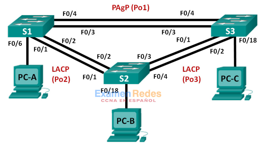
Tabla de asignación de direcciones
| Dispositivo | Interfaz | Dirección IP | Máscara de subred |
|---|---|---|---|
| S1 | VLAN 99 | 192.168.99.11 | 255.255.255.0 |
| S2 | VLAN 99 | 192.168.99.12 | 255.255.255.0 |
| S3 | VLAN 99 | 192.168.99.13 | 255.255.255.0 |
| PC-A | NIC | 192.168.10.1 | 255.255.255.0 |
| PC-B | NIC | 192.168.10.2 | 255.255.255.0 |
| PC-C | NIC | 192.168.10.3 | 255.255.255.0 |
Objetivos
Parte 1: Configurar los parámetros básicos del switch
Parte 2: configurar PAgP
Parte 3: configurar LACP
Información básica/situación
La agregación de enlaces permite la creación de enlaces lógicos que se componen de dos o más enlaces físicos. Esto proporciona un mayor rendimiento más allá del uso de un único enlace físico. Si uno de los enlaces falla, la agregación de enlaces también proporciona redundancia.
En esta práctica de laboratorio, configurará EtherChannel, una forma de agregación de enlaces que se utiliza en las redes conmutadas. Configurará EtherChannel mediante el protocolo de agregación de puertos (PAgP) y el protocolo de control de agregación de enlaces (LACP).
Nota: PAgP es un protocolo exclusivo de Cisco que solo se puede ejecutar en switches Cisco y en switches que sean de proveedores con licencia para admitir PAgP. LACP es un protocolo de agregación de enlaces definido en IEEE 802.3ad y no se asocia a ningún proveedor específico.
LACP permite que los switches Cisco administren los canales Ethernet entre los switches que cumplen con el protocolo 802.3ad. Puede configurar hasta 16 puertos para formar un canal. Ocho de los puertos están en modo activo y los otros ocho están en modo de espera. Cuando falla alguno de los puertos activos, se activa un puerto en espera. El modo de espera funciona solo para LACP, no para PAgP.
Nota: los switches que se utilizan en las prácticas de laboratorio de CCNA son Cisco Catalyst 2960s con IOS de Cisco versión 15.0(2) (imagen lanbasek9). Se pueden utilizar otros switches y otras versiones del IOS de Cisco. Según el modelo y la versión de IOS de Cisco, los comandos disponibles y los resultados que se obtienen pueden diferir de los que se muestran en las prácticas de laboratorio.
Nota: asegúrese de que los switches se hayan borrado y que no tengan configuraciones de inicio. Si no está seguro, consulte al instructor.
Nota para el instructor: consulte el Manual de prácticas de laboratorio para el instructor a fin de conocer los procedimientos para inicializar y volver a cargar los dispositivos.
Recursos necesarios
• 3 switches (Cisco 2960 con IOS de Cisco versión 15.0(2), imagen lanbasek9 o similar)
• 3 computadoras (Windows 7, Vista o XP con un programa de emulación de terminal, como Tera Term)
• Cables de consola para configurar los dispositivos con IOS de Cisco mediante los puertos de consola
• Cables Ethernet, como se muestra en la topología
Parte 1: Configurar los parámetros básicos del switch
En la parte 1, configurará la topología de la red y los parámetros básicos, como direcciones IP de la interfaz, el acceso a dispositivos y contraseñas.
Paso 1: Realizar el cableado de red tal como se muestra en la topología.
Conecte los dispositivos que se muestran en el diagrama de la topología y realice el cableado según sea necesario.
Paso 2: inicializar y volver a cargar los switches.
Paso 3: Configure los parámetros básicos para cada switch.
a. Desactive la búsqueda del DNS.
b. Configure el nombre del dispositivo como se muestra en la topología.
c. Cifre las contraseñas de texto no cifrado.
d. Cree un mensaje MOTD que advierta a los usuarios que se prohíbe el acceso no autorizado.
e. Asigne class como la contraseña cifrada del modo EXEC privilegiado.
f. Asigne cisco como la contraseña de vty y de la consola, y habilite el inicio de sesión.
g. Configure logging synchronous para evitar que un mensaje de consola interrumpa la entrada de comandos.
h. Desactive todos los puertos del switch, excepto los puertos conectados a computadoras.
i. Configure la VLAN 99 y asígnele el nombre Management.
j. Configure la VLAN 10 y asígnele el nombre Staff.
k. Configure los puertos del switch con hosts conectados como puertos de acceso en la VLAN 10.
l. Asigne el direccionamiento IP según la tabla de direccionamiento.
m. Copie la configuración en ejecución en la configuración de inicio.
Paso 4: Configurar las PC.
Asigne direcciones IP a las computadoras según la tabla de direccionamiento.
Parte 2: Configurar PAgP
PAgP es un protocolo exclusivo de Cisco para la agregación de enlaces. En la parte 2, se configurará un enlace entre el S1 y el S3 mediante PAgP.
Paso 1: Configurar PAgP en el S1 y el S3.
Para establecer un enlace entre el S1 y el S3, configure los puertos en el S1 con modo deseado de PAgP y los puertos en el S3 con modo automático de PAgP. Habilite los puertos después de que se configuren los modos PAgP.
S1(config)# interface range f0/3-4
S1(config-if-range)# channel-group 1 mode desirable
Creating a port-channel interface Port-channel 1

S1(config-if-range)# no shutdown

S3(config)# interface range f0/3-4
S3(config-if-range)# channel-group 1 mode auto
Creating a port-channel interface Port-channel 1

S3(config-if-range)# no shutdown
*Mar 1 00:09:12.792: %LINK-3-UPDOWN: Interface FastEthernet0/3, changed state to up
*Mar 1 00:09:12.792: %LINK-3-UPDOWN: Interface FastEthernet0/4, changed state to up
S3(config-if-range)#
*Mar 1 00:09:15.384: %LINEPROTO-5-UPDOWN: Line protocol on Interface FastEthernet0/3,
changed state to up
*Mar 1 00:09:16.265: %LINEPROTO-5-UPDOWN: Line protocol on Interface FastEthernet0/4,
changed state to up
S3(config-if-range)#
*Mar 1 00:09:16.357: %LINK-3-UPDOWN: Interface Port-channel1, changed state to up
*Mar 1 00:09:17.364: %LINEPROTO-5-UPDOWN: Line protocol on Interface Port-channel1,
changed state to up
*Mar 1 00:09:44.383: %LINEPROTO-5-UPDOWN: Line protocol on Interface Vlan1, changed
state to up
Paso 2: Examinar la configuración en los puertos.
Actualmente, las interfaces F0/3, F0/4 y Po1 (canal de puertos 1) en el S1 y el S3 están en modo operativo de acceso con el modo administrativo en dinámico automático. Verifique la configuración mediante los comandos show run interface id-interfaz y show interfaces id-interfaz switchport, respectivamente. Los resultados de configuración de ejemplo para F0/3 en el S1 son los siguientes:
S1# show run interface f0/3
Building configuration...

Current configuration : 103 bytes
!
interface FastEthernet0/3
 channel-group 1 mode desirable

S1# show interfaces f0/3 switchport
Name: Fa0/3
Switchport: Enabled
Administrative Mode: dynamic auto
Operational Mode: static access (member of bundle Po1)
Administrative Trunking Encapsulation: dot1q
Operational Trunking Encapsulation: native
Negotiation of Trunking: On
Access Mode VLAN: 1 (default)
Trunking Native Mode VLAN: 1 (default)
Administrative Native VLAN tagging: enabled
Voice VLAN: none
Administrative private-vlan host-association: none
Administrative private-vlan mapping: none
Administrative private-vlan trunk native VLAN: none
Administrative private-vlan trunk Native VLAN tagging: enabled
Administrative private-vlan trunk encapsulation: dot1q
Administrative private-vlan trunk normal VLANs: none
Administrative private-vlan trunk associations: none
Administrative private-vlan trunk mappings: none
Operational private-vlan: none
Trunking VLANs Enabled: ALL
Pruning VLANs Enabled: 2-1001
Capture Mode Disabled
Capture VLANs Allowed: ALL

Protected: false
Unknown unicast blocked: disabled
Unknown multicast blocked: disabled
Appliance trust: none
Paso 3: Verificar que se hayan agregado los puertos.
S1# show etherchannel summary
Flags:  D - down        P - bundled in port-channel
        I - stand-alone s - suspended
        H - Hot-standby (LACP only)
        R - Layer3      S - Layer2
        U - in use      f - failed to allocate aggregator

        M - not in use, minimum links not met
        u - unsuitable for bundling
        w - waiting to be aggregated
        d - default port

Number of channel-groups in use: 1
Number of aggregators:           1

Group  Port-channel  Protocol    Ports
------+-------------+-----------+-----------------------------------------------
1      Po1(SU)         PAgP      Fa0/3(P)    Fa0/4(P)

S3# show etherchannel summary
Flags:  D - down        P - bundled in port-channel
        I - stand-alone s - suspended
        H - Hot-standby (LACP only)
        R - Layer3      S - Layer2
        U - in use      f - failed to allocate aggregator

        M - not in use, minimum links not met
        u - unsuitable for bundling
        w - waiting to be aggregated
        d - default port

Number of channel-groups in use: 1
Number of aggregators:           1

Group  Port-channel  Protocol    Ports
------+-------------+-----------+-----------------------------------------------
1      Po1(SU)         PAgP      Fa0/3(P)    Fa0/4(P)
¿Qué significan los indicadores SU y P en el resumen de Ethernet?
El indicador P significa que los puertos están agrupados en un canal de puertos. El indicador S significa que el canal de puertos es un EtherChannel de capa 2. El indicador U significa que el EtherChannel está en uso.
Paso 4: Configurar los puertos de enlace troncal.
Una vez que se agregaron los puertos, los comandos aplicados a la interfaz de canal de puertos afectan a todos los enlaces que se agruparon. Configure manualmente los puertos Po1 en el S1 y el S3 como puertos de enlace troncal y asígnelos a la VLAN 99 nativa.
S1(config)# interface port-channel 1
S1(config-if)# switchport mode trunk
S1(config-if)# switchport trunk native vlan 99

S3(config)# interface port-channel 1
S3(config-if)# switchport mode trunk
S3(config-if)# switchport trunk native vlan 99
Paso 5: Verificar que los puertos estén configurados como puertos de enlace troncal.
a. Emita los comandos show run interface id-interfaz en el S1 y el S3. ¿Qué comandos se indican para F0/3 y F0/4 en ambos switches? ¿Compare los resultados con la configuración en ejecución para la interfaz Po1? Registre la observación.
switchport trunk native vlan 99
switchport mode trunk
Los comandos relacionados con la configuración de enlaces troncales son los mismos. Cuando se aplicaron los comandos de los enlaces troncales al EtherChannel, también afectaron los enlaces individuales en el grupo.
S1# show run interface po1
Building configuration...

Current configuration : 92 bytes
!
interface Port-channel1
 switchport trunk native vlan 99
 switchport mode trunk
end

S1# show run interface f0/3
Building configuration...

Current configuration : 126 bytes
!
interface FastEthernet0/3
 switchport trunk native vlan 99
 switchport mode trunk
channel-group 1 mode desirable
end
b. Emita los comandos show interfaces trunk y show spanning-tree en el S1 y el S3. ¿Qué puerto de enlace troncal se indica? ¿Cuál es la VLAN nativa? ¿Cuál es la conclusión del resultado?
El puerto de enlace troncal que se indica es Po1. La VLAN nativa es la 99. Una vez que se agrupan los enlaces, solo la interfaz agregada se indica en algunos comandos show.
Según el resultado de show spanning-tree, ¿cuál es el costo y la prioridad de puerto para el enlace agregado?
El costo de puerto para Po1 es 12, y la prioridad de puerto es 128.
S1# show interfaces trunk

Port        Mode             Encapsulation  Status        Native vlan
Po1         on               802.1q         trunking      99

Port        Vlans allowed on trunk
Po1         1-4094

Port        Vlans allowed and active in management domain
Po1         1,10,99

Port        Vlans in spanning tree forwarding state and not pruned
Po1         1,10,99

S3# show interfaces trunk

Port        Mode             Encapsulation  Status        Native vlan
Po1         on               802.1q         trunking      99

Port        Vlans allowed on trunk
Po1         1-4094

Port        Vlans allowed and active in management domain
Po1         1,10,99

Port        Vlans in spanning tree forwarding state and not pruned
Po1         1,10,99

S1# show spanning-tree

VLAN0001
  Spanning tree enabled protocol ieee
  Root ID    Priority    32769
             Address     0cd9.96e8.7400
             Cost        12
             Port        64 (Port-channel1)
             Hello Time   2 sec  Max Age 20 sec  Forward Delay 15 sec
  Bridge ID  Priority    32769  (priority 32768 sys-id-ext 1)
             Address     0cd9.96e8.8a00
             Hello Time   2 sec  Max Age 20 sec  Forward Delay 15 sec
             Aging Time  300 sec

Interface           Role Sts Cost      Prio.Nbr Type
------------------- ---- --- --------- -------- --------------------------------
Po1                 Root FWD 12        128.64   P2p

VLAN0010
  Spanning tree enabled protocol ieee
  Root ID    Priority    32778
             Address     0cd9.96e8.7400
             Cost        12
             Port        64 (Port-channel1)
             Hello Time   2 sec  Max Age 20 sec  Forward Delay 15 sec

  Bridge ID  Priority    32778  (priority 32768 sys-id-ext 10)
             Address     0cd9.96e8.8a00
             Hello Time   2 sec  Max Age 20 sec  Forward Delay 15 sec
             Aging Time  300 sec

Interface           Role Sts Cost      Prio.Nbr Type
------------------- ---- --- --------- -------- --------------------------------
Fa0/6               Desg FWD 19        128.6    P2p
Po1                 Root FWD 12        128.64   P2p

VLAN0099
  Spanning tree enabled protocol ieee
  Root ID    Priority    32867
             Address     0cd9.96e8.7400
             Cost        12
             Port        64 (Port-channel1)
             Hello Time   2 sec  Max Age 20 sec  Forward Delay 15 sec

  Bridge ID  Priority    32867  (priority 32768 sys-id-ext 99)
             Address     0cd9.96e8.8a00
             Hello Time   2 sec  Max Age 20 sec  Forward Delay 15 sec
             Aging Time  300 sec

Interface           Role Sts Cost      Prio.Nbr Type
------------------- ---- --- --------- -------- --------------------------------
Po1                 Root FWD 12        128.64   P2p

S3# show spanning-tree

VLAN0001
  Spanning tree enabled protocol ieee
  Root ID    Priority    32769
             Address     0cd9.96e8.7400
             This bridge is the root
             Hello Time   2 sec  Max Age 20 sec  Forward Delay 15 sec

  Bridge ID  Priority    32769  (priority 32768 sys-id-ext 1)
             Address     0cd9.96e8.7400
             Hello Time   2 sec  Max Age 20 sec  Forward Delay 15 sec
             Aging Time  300 sec

Interface           Role Sts Cost      Prio.Nbr Type
------------------- ---- --- --------- -------- --------------------------------
Po1                 Desg FWD 12        128.64   P2p

VLAN0010
  Spanning tree enabled protocol ieee
  Root ID    Priority    32778
             Address     0cd9.96e8.7400
             This bridge is the root
             Hello Time   2 sec  Max Age 20 sec  Forward Delay 15 sec

  Bridge ID  Priority    32778  (priority 32768 sys-id-ext 10)
             Address     0cd9.96e8.7400
             Hello Time   2 sec  Max Age 20 sec  Forward Delay 15 sec
             Aging Time  300 sec

Interface           Role Sts Cost      Prio.Nbr Type
------------------- ---- --- --------- -------- --------------------------------
Fa0/18              Desg FWD 19        128.18   P2p
Po1                 Desg FWD 12        128.64   P2p

VLAN0099
  Spanning tree enabled protocol ieee
  Root ID    Priority    32867
             Address     0cd9.96e8.7400
             This bridge is the root
             Hello Time   2 sec  Max Age 20 sec  Forward Delay 15 sec

  Bridge ID  Priority    32867  (priority 32768 sys-id-ext 99)
             Address     0cd9.96e8.7400
             Hello Time   2 sec  Max Age 20 sec  Forward Delay 15 sec
             Aging Time  300 sec

Interface           Role Sts Cost      Prio.Nbr Type
------------------- ---- --- --------- -------- --------------------------------
Po1                 Desg FWD 12        128.64   P2p
Parte 3: Configurar LACP
LACP es un protocolo de código abierto que desarrolló el IEEE para la agregación de enlaces. En la parte 3, se configurará el enlace entre el S1y el S2, así como el enlace entre el S2 y el S3, mediante LACP. Además, se configurarán los enlaces individuales como enlaces troncales antes de que se agrupen como EtherChannels.
Paso 1: Configurar LACP entre el S1 y el S2.
S1(config)# interface range f0/1-2
S1(config-if-range)# switchport mode trunk
S1(config-if-range)# switchport trunk native vlan 99
S1(config-if-range)# channel-group 2 mode active
Creating a port-channel interface Port-channel 2

S1(config-if-range)# no shutdown

S2(config)# interface range f0/1-2
S2(config-if-range)# switchport mode trunk
S2(config-if-range)# switchport trunk native vlan 99
S2(config-if-range)# channel-group 2 mode passive
Creating a port-channel interface Port-channel 2

S2(config-if-range)# no shutdown
Paso 2: Verificar que se hayan agregado los puertos.
¿Qué protocolo usa Po2 para la agregación de enlaces? ¿Qué puertos se agregaron para formar Po2?
Registre el comando que se utilizó para verificar.
Po2 usa LACP, y se agregaron F0/1 y F0/2 para formar Po2.
S1# show etherchannel summary
Flags:  D - down        P - bundled in port-channel
        I - stand-alone s - suspended
        H - Hot-standby (LACP only)
        R - Layer3      S - Layer2
        U - in use      f - failed to allocate aggregator

        M - not in use, minimum links not met
        u - unsuitable for bundling
        w - waiting to be aggregated
        d - default port

Number of channel-groups in use: 2
Number of aggregators:           2

Group  Port-channel  Protocol    Ports
------+-------------+-----------+-----------------------------------------------
1      Po1(SU)         PAgP      Fa0/3(P)    Fa0/4(P)
2      Po2(SU)         LACP      Fa0/1(P)    Fa0/2(P)

S2# show etherchannel summary
Flags:  D - down        P - bundled in port-channel
        I - stand-alone s - suspended
        H - Hot-standby (LACP only)
        R - Layer3      S - Layer2
        U - in use      f - failed to allocate aggregator

        M - not in use, minimum links not met
        u - unsuitable for bundling
        w - waiting to be aggregated
        d - default port

Number of channel-groups in use: 1
Number of aggregators:           1

Group  Port-channel  Protocol    Ports
------+-------------+-----------+-----------------------------------------------
2      Po2(SU)         LACP      Fa0/1(P)    Fa0/2(P)
Paso 3: Configurar LACP entre el S2 y el S3.
a. Configure el enlace entre el S2 y el S3 como Po3 y use LACP como protocolo de agregación de enlaces.
S2(config)# interface range f0/3-4
S2(config-if-range)# switchport mode trunk
S2(config-if-range)# switchport trunk native vlan 99
S2(config-if-range)# channel-group 3 mode active
Creating a port-channel interface Port-channel 3
S2(config-if-range)# no shutdown

S3(config)# interface range f0/1-2
S3(config-if-range)# switchport mode trunk
S3(config-if-range)# switchport trunk native vlan 99
S3(config-if-range)# channel-group 3 mode passive
Creating a port-channel interface Port-channel 3

S3(config-if-range)# no shutdown
b. Verifique que se haya formado el EtherChannel.
S2# show etherchannel summary
Flags:  D - down        P - bundled in port-channel
        I - stand-alone s - suspended
        H - Hot-standby (LACP only)
        R - Layer3      S - Layer2
        U - in use      f - failed to allocate aggregator

        M - not in use, minimum links not met
        u - unsuitable for bundling
        w - waiting to be aggregated
        d - default port

Number of channel-groups in use: 2
Number of aggregators:           2

Group  Port-channel  Protocol    Ports
------+-------------+-----------+-----------------------------------------------
2      Po2(SU)         LACP      Fa0/1(P)    Fa0/2(P)
3      Po3(SU)         LACP      Fa0/3(P)    Fa0/4(P)

S3# show etherchannel summary
Flags:  D - down        P - bundled in port-channel
        I - stand-alone s - suspended
        H - Hot-standby (LACP only)
        R - Layer3      S - Layer2
        U - in use      f - failed to allocate aggregator

        M - not in use, minimum links not met
        u - unsuitable for bundling
        w - waiting to be aggregated
        d - default port

Number of channel-groups in use: 2
Number of aggregators:           2

Group  Port-channel  Protocol    Ports
------+-------------+-----------+-----------------------------------------------
1      Po1(SU)         PAgP      Fa0/3(P)    Fa0/4(P)
3      Po3(SU)         LACP      Fa0/1(P)    Fa0/2(P)
Paso 4: Verifique la conectividad de extremo a extremo.
Verifique que todos los dispositivos puedan hacer ping entre sí dentro de la misma VLAN. De lo contrario, lleve a cabo la resolución de problemas hasta que haya conectividad de extremo a extremo.
Nota: puede ser necesario inhabilitar el firewall del equipo para hacer ping entre los equipos.
Reflexión
¿Qué podría evitar que se formen los EtherChannels?
Una incompatibilidad en la configuración (como un puerto de enlace troncal en un extremo y un puerto de acceso en el otro extremo, diferentes protocolos de agregación y diferente velocidad de puertos o dúplex) evitaría la formación de un EtherChannel.
Configuraciones de dispositivos
- Switch S1
- Switch S2
- Switch S3
S1# show vlan brief

VLAN Name                             Status    Ports
---- -------------------------------- --------- -------------------------------
1    default                          active    Fa0/5, Fa0/7, Fa0/8, Fa0/9
                                                Fa0/10, Fa0/11, Fa0/12, Fa0/13
                                                Fa0/14, Fa0/15, Fa0/16, Fa0/17
                                                Fa0/18, Fa0/19, Fa0/20, Fa0/21
                                                Fa0/22, Fa0/23, Fa0/24, Gi0/1
                                                Gi0/2
10   Staff                            active    Fa0/6
99   Management                       active
1002 fddi-default                     act/unsup
1003 token-ring-default               act/unsup
1004 fddinet-default                  act/unsup
1005 trnet-default                    act/unsup

S1# show run
Building configuration...

Current configuration : 2339 bytes
!
version 15.0
no service pad
service timestamps debug datetime msec
service timestamps log datetime msec
service password-encryption
!
hostname S1
!
boot-start-marker
boot-end-marker
!
enable secret 4 06YFDUHH61wAE/kLkDq9BGho1QM5EnRtoyr8cHAUg.2
!
no aaa new-model
system mtu routing 1500
!
!
no ip domain-lookup
!
!
!
!
!
!
!
!
spanning-tree mode pvst
spanning-tree extend system-id
!
vlan internal allocation policy ascending
!
!
!
!
!
!
interface Port-channel1
switchport trunk native vlan 99
switchport mode trunk
!
interface Port-channel2
switchport trunk native vlan 99
switchport mode trunk
!
interface FastEthernet0/1
switchport trunk native vlan 99
switchport mode trunk
channel-group 2 mode active
!
interface FastEthernet0/2
switchport trunk native vlan 99
switchport mode trunk
channel-group 2 mode active
!
interface FastEthernet0/3
switchport trunk native vlan 99
switchport mode trunk
channel-group 1 mode desirable
!
interface FastEthernet0/4
switchport trunk native vlan 99
switchport mode trunk
channel-group 1 mode desirable
!
interface FastEthernet0/5
shutdown
!
interface FastEthernet0/6
switchport access vlan 10
switchport mode access
!
interface FastEthernet0/7
shutdown
!
interface FastEthernet0/8
shutdown
!
interface FastEthernet0/9
shutdown
!
interface FastEthernet0/10
shutdown
!
interface FastEthernet0/11
shutdown
!
interface FastEthernet0/12
shutdown
!
interface FastEthernet0/13
shutdown
!
interface FastEthernet0/14
shutdown
!
interface FastEthernet0/15
shutdown
!
interface FastEthernet0/16
shutdown
!
interface FastEthernet0/17
shutdown
!
interface FastEthernet0/18
shutdown
!
interface FastEthernet0/19
shutdown
!
interface FastEthernet0/20
shutdown
!
interface FastEthernet0/21
shutdown
!
interface FastEthernet0/22
shutdown
!
interface FastEthernet0/23
shutdown
!
interface FastEthernet0/24
shutdown
!
interface GigabitEthernet0/1
shutdown
!
interface GigabitEthernet0/2
shutdown
!
interface Vlan1
no ip address
!
interface Vlan99
ip address 192.168.99.11 255.255.255.0
!
ip http server
ip http secure-server
!
!
banner motd ^C
Unauthorized Access Prohibited.^C
!
line con 0
password 7 0822455D0A16
logging synchronous
login
line vty 0 4
password 7 0822455D0A16
login
line vty 5 15
password 7 1511021F0725
login
!
end
S2# show vlan brief

VLAN Name                             Status    Ports
---- -------------------------------- --------- -------------------------------
1    default                          active    Fa0/5, Fa0/6, Fa0/7, Fa0/8
                                                Fa0/9, Fa0/10, Fa0/11, Fa0/12
                                                Fa0/13, Fa0/14, Fa0/15, Fa0/16
                                                Fa0/17, Fa0/19, Fa0/20, Fa0/21
                                                Fa0/22, Fa0/23, Fa0/24, Gi0/1
                                                Gi0/2
10   Staff                            active    Fa0/18
99   Management                       active
1002 fddi-default                     act/unsup
1003 token-ring-default               act/unsup
1004 fddinet-default                  act/unsup
1005 trnet-default                    act/unsup

S2# show run
Building configuration...

Current configuration : 2333 bytes
!
version 15.0
no service pad
service timestamps debug datetime msec
service timestamps log datetime msec
service password-encryption
!
hostname S2
!
boot-start-marker
boot-end-marker
!
enable secret 4 06YFDUHH61wAE/kLkDq9BGho1QM5EnRtoyr8cHAUg.2
!
no aaa new-model
system mtu routing 1500
!
!
no ip domain-lookup
!
!
!
!
!
!
!
!
spanning-tree mode pvst
spanning-tree extend system-id
!
vlan internal allocation policy ascending
!
!
!
!
!
!
interface Port-channel2
switchport trunk native vlan 99
switchport mode trunk
!
interface Port-channel3
switchport trunk native vlan 99
switchport mode trunk
!
interface FastEthernet0/1
switchport trunk native vlan 99
switchport mode trunk
channel-group 2 mode passive
!
interface FastEthernet0/2
switchport trunk native vlan 99
switchport mode trunk
channel-group 2 mode passive
!
interface FastEthernet0/3
switchport trunk native vlan 99
switchport mode trunk
channel-group 3 mode active
!
interface FastEthernet0/4
switchport trunk native vlan 99
switchport mode trunk
channel-group 3 mode active
!
interface FastEthernet0/5
shutdown
!
interface FastEthernet0/6
shutdown
!
interface FastEthernet0/7
shutdown
!
interface FastEthernet0/8
shutdown
!
interface FastEthernet0/9
shutdown
!
interface FastEthernet0/10
shutdown
!
interface FastEthernet0/11
shutdown
!
interface FastEthernet0/12
shutdown
!
interface FastEthernet0/13
shutdown
!
interface FastEthernet0/14
shutdown
!
interface FastEthernet0/15
shutdown
!
interface FastEthernet0/16
shutdown
!
interface FastEthernet0/17
shutdown
!
interface FastEthernet0/18
switchport access vlan 10
switchport mode access
!
interface FastEthernet0/19
shutdown
!
interface FastEthernet0/20
shutdown
!
interface FastEthernet0/21
shutdown
!
interface FastEthernet0/22
shutdown
!
interface FastEthernet0/23
shutdown
!
interface FastEthernet0/24
shutdown
!
interface GigabitEthernet0/1
shutdown
!
interface GigabitEthernet0/2
shutdown
!
interface Vlan1
no ip address
!
interface Vlan99
ip address 192.168.99.12 255.255.255.0
!
ip http server
ip http secure-server
!
banner motd ^C
Unauthorized Access Prohibited.^C
!
line con 0
password 7 060506324F41
logging synchronous
login
line vty 0 4
password 7 060506324F41
login
line vty 5 15
password 7 121A0C041104
login
!
end
S3# show vlan brief

VLAN Name                             Status    Ports
---- -------------------------------- --------- -------------------------------
1    default                          active    Fa0/5, Fa0/6, Fa0/7, Fa0/8
                                                Fa0/9, Fa0/10, Fa0/11, Fa0/12
                                                Fa0/13, Fa0/14, Fa0/15, Fa0/16
                                                Fa0/17, Fa0/19, Fa0/20, Fa0/21
                                                Fa0/22, Fa0/23, Fa0/24, Gi0/1
                                                Gi0/2
10   Staff                            active    Fa0/18
99   Management                       active
1002 fddi-default                     act/unsup
1003 token-ring-default               act/unsup
1004 fddinet-default                  act/unsup
1005 trnet-default                    act/unsup

S3# show run
Building configuration...

Current configuration : 2331 bytes
!
version 15.0
no service pad
service timestamps debug datetime msec
service timestamps log datetime msec
service password-encryption
!
hostname S3
!
boot-start-marker
boot-end-marker
!
enable secret 4 06YFDUHH61wAE/kLkDq9BGho1QM5EnRtoyr8cHAUg.2
!
no aaa new-model
system mtu routing 1500
!
!
no ip domain-lookup
!
!
!
!
!
!
!
!
spanning-tree mode pvst
spanning-tree extend system-id
!
vlan internal allocation policy ascending
!
!
!
!
!
!
interface Port-channel1
switchport trunk native vlan 99
switchport mode trunk
!
interface Port-channel3
switchport trunk native vlan 99
switchport mode trunk
!
interface FastEthernet0/1
switchport trunk native vlan 99
switchport mode trunk
channel-group 3 mode passive
!
interface FastEthernet0/2
switchport trunk native vlan 99
switchport mode trunk
channel-group 3 mode passive
!
interface FastEthernet0/3
switchport trunk native vlan 99
switchport mode trunk
channel-group 1 mode auto
!
interface FastEthernet0/4
switchport trunk native vlan 99
switchport mode trunk
channel-group 1 mode auto
!
interface FastEthernet0/5
shutdown
!
interface FastEthernet0/6
shutdown
!
interface FastEthernet0/7
shutdown
!
interface FastEthernet0/8
shutdown
!
interface FastEthernet0/9
shutdown
!
interface FastEthernet0/10
shutdown
!
interface FastEthernet0/11
shutdown
!
interface FastEthernet0/12
shutdown
!
interface FastEthernet0/13
shutdown
!
interface FastEthernet0/14
shutdown
!
interface FastEthernet0/15
shutdown
!
interface FastEthernet0/16
shutdown
!
interface FastEthernet0/17
shutdown
!
interface FastEthernet0/18
switchport access vlan 10
switchport mode access
!
interface FastEthernet0/19
shutdown
!
interface FastEthernet0/20
shutdown
!
interface FastEthernet0/21
shutdown
!
interface FastEthernet0/22
shutdown
!
interface FastEthernet0/23
shutdown
!
interface FastEthernet0/24
shutdown
!
interface GigabitEthernet0/1
shutdown
!
interface GigabitEthernet0/2
shutdown
!
interface Vlan1
no ip address
!
interface Vlan99
ip address 192.168.99.13 255.255.255.0
!
ip http server
ip http secure-server
!
!
banner motd ^C
Unauthorized Access Prohibited.^C
!
line con 0
password 7 045802150C2E
logging synchronous
login
line vty 0 4
password 7 110A1016141D
login
line vty 5 15
password 7 070C285F4D06
login
!
end