Última actualización: septiembre 8, 2022
8.2.3.6 Práctica de laboratorio: Resolución de problemas de EIGRP básico para IPv4 e IPv6 (versión para el instructor)
Nota para el instructor: el color de fuente rojo o las partes resaltadas en gris indican texto que aparece en la copia del instructor solamente.
Topología
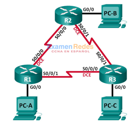
Tabla de asignación de direcciones
| Dispositivo | Id. de router EIGRP | Interfaz | Dirección IP | Gateway predeterminado |
|---|---|---|---|---|
| R1 | 1.1.1.1 | G0/0 | 192.168.1.1/24 2001:DB8:ACAD:A::1/64 FE80::1 link-local |
N/A |
| S0/0/0 (DCE) | 192.168.12.1/30 2001:DB8:ACAD:12::1/64 FE80::1 link-local |
N/A | ||
| S0/0/1 | 192.18.13.1/30 2001:DB8:ACAD:13::1/64 FE80::1 link-local |
N/A | ||
| R2 | 2.2.2.2 | G0/0 | 192.168.2.1/24 2001:DB8:ACAD:B::2/64 FE80::2 link-local |
N/A |
| S0/0/0 | 192.168.12.2/30 2001:DB8:ACAD:12::2/64 FE80::2 link-local |
N/A | ||
| S0/0/1 (DCE) | 192.168.23.1/30 2001:DB8:ACAD:23::2/64 FE80::2 link-local |
N/A | ||
| R3 | 3.3.3.3 | G0/0 | 192.168.3.1/24 2001:DB8:ACAD:C::3/64 FE80::3 link-local |
N/A |
| S0/0/0 (DCE) | 192.168.13.2/30 2001:DB8:ACAD:13::3/64 FE80::3 link-local |
N/A | ||
| S0/0/1 | 192.168.23.2/30 2001:DB8:ACAD:23::3/64 FE80::3 link-local |
N/A | ||
| PC-A | NIC | 192.168.1.3/24 2001:DB8:ACAD:A::A/64 |
192.168.1.1 FE80::1 |
|
| PC-B | NIC | 192.168.2.3/24 2001:DB8:ACAD:B::B/64 |
192.168.2.1 FE80::2 |
|
| PC-C | NIC | 192.168.3.3/24 2001:DB8:ACAD:C::C/64 |
192.168.3.1 FE80::3 |
Objetivos
Parte 1: armar la red y cargar las configuraciones de los dispositivos
Parte 2: Resolver problemas de conectividad de capa 3
Parte 3: Resolver problemas de EIGRP para IPv4
Parte 4: Resolver problemas de EIGRP para IPv6
Información básica/situación
El protocolo de routing de gateway interior mejorado (EIGRP) es un protocolo de routing vector distancia avanzado desarrollado por Cisco Systems. Los routers EIGRP descubren vecinos y establecen y mantienen adyacencias con los routers vecinos mediante paquetes de saludo. Un router EIGRP supone que, mientras reciba paquetes de saludo de un router vecino, el vecino está activo y sus rutas siguen siendo viables.
EIGRP para IPv4 se ejecuta a través de la capa de red IPv4, por lo que se comunica con otros peers IPv4 EIGRP y solo anuncia rutas IPv4. EIGRP para IPv6 tiene la misma funcionalidad que EIGRP para IPv4, pero utiliza IPv6 como el protocolo de capa de red, se comunica con peers EIGRP para IPv6 y anuncia rutas IPv6.
En esta práctica de laboratorio, resolverá problemas en una red que ejecuta los protocolos de routing EIGRP para IPv4 y EIGRP para IPv6. Esta red presenta problemas, y se le asigna la tarea de encontrarlos y corregirlos.
Nota: los routers que se utilizan en las prácticas de laboratorio de CCNA son routers de servicios integrados (ISR) Cisco 1941 con IOS de Cisco versión 15.2(4)M3 (imagen universalk9). Pueden utilizarse otros routers y otras versiones del IOS de Cisco. Según el modelo y la versión de IOS de Cisco, los comandos disponibles y los resultados que se obtienen pueden diferir de los que se muestran en las prácticas de laboratorio. Consulte la tabla Resumen de interfaces del router que se encuentra al final de esta práctica de laboratorio para obtener los identificadores de interfaz correctos.
Nota: asegúrese de que los routers se hayan borrado y no tengan configuraciones de inicio. Si no está seguro, consulte al instructor.
Nota para el instructor: consulte el Manual de prácticas de laboratorio para el instructor a fin de conocer los procedimientos para inicializar y volver a cargar los dispositivos.
Recursos necesarios
• 3 routers (Cisco 1941 con IOS de Cisco versión 15.2(4)M3, imagen universal o similar)
• 3 computadoras (Windows 7, Vista o XP con un programa de emulación de terminal, como Tera Term)
• Cables de consola para configurar los dispositivos con IOS de Cisco mediante los puertos de consola
• Cables Ethernet y seriales, como se muestra en la topología.
Parte 1: armar la red y cargar las configuraciones de los dispositivos
En la parte 1, establecerá la topología de la red y configurará los parámetros básicos en los equipos host y los routers.
Paso 1: Realizar el cableado de red tal como se muestra en la topología.
Paso 2: Configure los host del equipo.
Paso 3: Cargue las configuraciones del router.
Cargue las siguientes configuraciones en el router apropiado. Todos los routers tienen las mismas contraseñas. La contraseña de EXEC privilegiado es class, y la contraseña de consola y de vty es cisco.
Configuración del router R1:
conf t
service password-encryption
hostname R1
enable secret class
no ip domain lookup
ipv6 unicast-routing
interface GigabitEthernet0/0
ip address 192.168.1.1 255.255.255.0
duplex auto
speed auto
ipv6 address FE80::1 link-local
ipv6 address 2001:DB8:ACAD:A::1/64
ipv6 eigrp 1
no shutdown
interface Serial0/0/0
bandwidth 128
ip address 192.168.21.1 255.255.255.252
!ip address 192.168.12.1 255.255.255.252
ipv6 address FE80::1 link-local
ipv6 address 2001:DB8:ACAD:12::1/64
ipv6 eigrp 1
clock rate 128000
no shutdown
interface Serial0/0/1
!bandwidth 128
ip address 192.168.13.1 255.255.255.252
ipv6 address FE80::1 link-local
ipv6 address 2001:DB8:ACAD:31::1/64
!ipv6 address 2001:DB8:ACAD:13::1/64
ipv6 eigrp 1
no shutdown
router eigrp 1
network 192.168.1.0
network 192.168.12.0 0.0.0.3
network 192.168.13.0 0.0.0.3
passive-interface GigabitEthernet0/0
eigrp router-id 1.1.1.1
ipv6 router eigrp 1
! router-id 1.1.1.1
!passive-interface GigabitEthernet0/0
no shutdown
banner motd @
Unauthorized Access is Prohibited! @
line con 0
password cisco
logging synchronous
line vty 0 4
password cisco
login
transport input all
end
Configuración del router R2:
conf t
service password-encryption
hostname R2
enable secret class
no ip domain lookup
ipv6 unicast-routing
interface GigabitEthernet0/0
ip address 192.168.2.1 255.255.255.0
duplex auto
speed auto
ipv6 address FE80::2 link-local
ipv6 address 2001:DB8:ACAD:B::2/64
ipv6 eigrp 1
! no shutdown
interface Serial0/0/0
! bandwidth 128
ip address 192.168.12.2 255.255.255.252
ipv6 address FE80::2 link-local
ipv6 address 2001:DB8:ACAD:12::2/64
ipv6 eigrp 1
no shutdown
interface Serial0/0/1
bandwidth 128
ip address 192.168.23.1 255.255.255.0
!ip address 192.168.23.1 255.255.255.252
ipv6 address FE80::2 link-local
ipv6 address 2001:DB8:ACAD:23::2/64
ipv6 eigrp 1
clock rate 128000
no shutdown
router eigrp 1
! network 192.168.2.0 0.0.0.255
network 192.168.12.0 0.0.0.3
network 192.168.23.0 0.0.0.3
passive-interface GigabitEthernet0/0
eigrp router-id 2.2.2.2
ipv6 router eigrp 1
! router-id 2.2.2.2
no shutdown
passive-interface GigabitEthernet0/0
banner motd @
Unauthorized Access is Prohibited! @
line con 0
password cisco
login
logging synchronous
line vty 0 4
password cisco
login
transport input all
end
Configuración del router R3:
conf t
service password-encryption
hostname R3
enable secret class
no ip domain lookup
! ipv6 unicast-routing
interface GigabitEthernet0/0
ip address 192.168.3.1 255.255.255.0
duplex auto
speed auto
ipv6 address FE80::3 link-local
ipv6 address 2001:DB8:ACAD:C::3/64
ipv6 eigrp 1
! no shutdown
interface Serial0/0/0
! bandwidth 128
ip address 192.168.13.2 255.255.255.252
ipv6 address FE80::3 link-local
ipv6 address 2001:DB8:ACAD:13::3/64
ipv6 eigrp 1
no shutdown
! clock rate 128000
interface Serial0/0/1
bandwidth 128
ip address 192.168.23.2 255.255.255.252
ipv6 address FE80::3 link-local
ipv6 address 2001:DB8:ACAD:23::3/64
ipv6 eigrp 1
no shutdown
router eigrp 1
network 192.168.3.0
network 192.168.13.0 0.0.0.3
! network 192.168.23.0 0.0.0.3
passive-interface GigabitEthernet0/0
eigrp router-id 3.3.3.3
!ipv6 router eigrp 1
! router-id 3.3.3.3
! passive-interface GigabitEthernet0/0
! no shutdown
banner motd @
Unauthorized Access is Prohibited! @
line con 0
password cisco
login
logging synchronous
line vty 0 4
password cisco
login
transport input all
end
Paso 4: Guardar la configuración en ejecución de todos los routers.
Parte 2: Resolver problemas de conectividad de capa 3
En la parte 2, verificará que se haya establecido la conectividad de capa 3 en todas las interfaces. Deberá probar tanto la conectividad IPv4 como IPv6 para todas las interfaces de los dispositivos.
Nota: todas las interfaces seriales deben tener un ancho de banda de 128 Kb/s. La frecuencia de reloj en la interfaz DCE debe ser de 128 000.
Paso 1: Verificar que las interfaces que se indican en la tabla de direccionamiento estén activas y configuradas con la información de dirección IP correcta.
a. Emita el comando show ip interface brief en todos los routers para verificar que las interfaces estén en estado up/up (activo/activo). Registre sus conclusiones.
R1: todas las interfaces activa/activa
R2: G0/0 está desactivado administrativamente
R3: G0/0 está desactivado administrativamente
R1# show ip interface brief
Interface                  IP-Address      OK? Method Status                Protocol
Embedded-Service-Engine0/0 unassigned      YES unset  administratively down down
GigabitEthernet0/0         192.168.1.1     YES manual up                    up
GigabitEthernet0/1         unassigned      YES unset  administratively down down
Serial0/0/0                192.168.21.1    YES manual up                    up
Serial0/0/1                192.168.13.1    YES manual up                    up

R2# show ip interface brief
Interface                  IP-Address      OK? Method Status                Protocol
Embedded-Service-Engine0/0 unassigned      YES unset  administratively down down
GigabitEthernet0/0         192.168.2.1     YES manual administratively down down
GigabitEthernet0/1         unassigned      YES unset  administratively down down
Serial0/0/0                192.168.12.2    YES manual up                    up
Serial0/0/1                192.168.23.1    YES manual up                    up

R3# show ip interface brief
Interface                  IP-Address      OK? Method Status                Protocol
Embedded-Service-Engine0/0 unassigned      YES unset  administratively down down
GigabitEthernet0/0         192.168.3.1     YES manual administratively down down
GigabitEthernet0/1         unassigned      YES unset  administratively down down
Serial0/0/0                192.168.13.2    YES manual up                    up
Serial0/0/1                192.168.23.2    YES manual up                    up
b. Emita el comando show run interface para verificar las asignaciones de direcciones IP en todas las interfaces del router. Compare las direcciones IP de las interfaces con la tabla de direccionamiento y verifique las asignaciones de máscara de subred. Para IPv6, verifique que se haya asignado la dirección link-local. Registre sus conclusiones.
R1: la dirección IPv4 de S0/0/0 es incorrecta, debería ser 192.168.12.1; la dirección IPv6 de S0/0/1 es incorrecta, debería ser 2001:DB8:ACAD:13::1/64.
R2: la máscara de subred de S0/0/1 es incorrecta, debería ser 255.255.255.252.
R3: todas las IP están configuradas correctamente.
R1# show run interface s0/0/0
Building configuration...

Current configuration : 188 bytes
!
interface Serial0/0/0
 bandwidth 128
 ip address 192.168.21.1 255.255.255.252
 ipv6 address FE80::1 link-local
 ipv6 address 2001:DB8:ACAD:12::1/64
 ipv6 eigrp 1
 clock rate 128000
end

R1# show run interface s0/0/1
Building configuration...

Current configuration : 154 bytes
!
interface Serial0/0/1
 ip address 192.168.13.1 255.255.255.252
 ipv6 address FE80::1 link-local
 ipv6 address 2001:DB8:ACAD:31::1/64
 ipv6 eigrp 1
end

R2# show run interface s0/0/1
Building configuration...

Current configuration : 186 bytes
!
interface Serial0/0/1
 bandwidth 128
 ip address 192.168.23.1 255.255.255.0
 ipv6 address FE80::2 link-local
 ipv6 address 2001:DB8:ACAD:23::2/64
 ipv6 eigrp 1
 clock rate 128000
end
c. Emita el comando show interfaces id-interfaz para verificar la configuración del ancho de banda en las interfaces seriales. Registre sus conclusiones.
R1: el ancho de banda de 1544 de S0/0/1 es incorrecto, debería ser 128.
R2: el ancho de banda de 1544 de S0/0/0 es incorrecto, debería ser 128.
R3: el ancho de banda de 1544 de S0/0/0 es incorrecto, debería ser 128.
R1# show interfaces s0/0/1
Serial0/0/1 is up, line protocol is up
  Hardware is WIC MBRD Serial
  Internet address is 192.168.13.1/30
  MTU 1500 bytes, BW 1544 Kbit/sec, DLY 20000 usec,
     reliability 255/255, txload 1/255, rxload 1/255
  Encapsulation HDLC, loopback not set
  Keepalive set (10 sec)
<resultado omitido>

R2# show interfaces s0/0/0
Serial0/0/0 is up, line protocol is up
  Hardware is WIC MBRD Serial
  Internet address is 192.168.12.2/30
  MTU 1500 bytes, BW 1544 Kbit/sec, DLY 20000 usec,
     reliability 255/255, txload 1/255, rxload 1/255
  Encapsulation HDLC, loopback not set
  Keepalive set (10 sec)
<resultado omitido>

R3# show interfaces s0/0/0
Serial0/0/0 is up, line protocol is up
  Hardware is WIC MBRD Serial
  Internet address is 192.168.13.2/30
  MTU 1500 bytes, BW 1544 Kbit/sec, DLY 20000 usec,
     reliability 255/255, txload 1/255, rxload 1/255
  Encapsulation HDLC, loopback not set
  Keepalive set (10 sec)
<resultado omitido>
d. Emita el comando show controllers id-interfaz para verificar que las frecuencias de reloj sean de 128 Kb/s en todas las interfaces seriales DCE. Emita el comando show interfaces id-interfaz para verificar la configuración del ancho de banda en las interfaces seriales. Registre sus conclusiones.
R1: la frecuencia de reloj está bien configurada en S0/0/0.
R2: la frecuencia de reloj está bien configurada en S0/0/1.
R3: la frecuencia de reloj de 2 000 000 en S0/0/0 es incorrecta, debería ser 128 000.
R3# show controllers s0/0/0
Interface Serial0/0/0
Hardware is SCC
DCE V.35, clock rate 2000000

idb at 0x30FE4FB4, driver data structure at 0x29E7C30C
wic_info 0x30FE5EC4
<resultado omitido>
e. Resuelva todos los problemas que detecte. Registre los comandos utilizados para corregir los problemas.
R1(config)# interface s0/0/0
R1(config-if)# ip address 192.168.12.1 255.255.255.252
R1(config-if)# interface s0/0/1
R1(config-if)# bandwidth 128
R1(config-if)# no ipv6 address 2001:db8:acad:31::1/64
R1(config-if)# ipv6 address 2001:db8:acad:13::1/64
R1(config-if)# end

R2(config)# interface g0/0
R2(config-if)# no shutdown
R2(config-if)# interface s0/0/0
R2(config-if)# bandwidth 128
R2(config-if)# interface s0/0/1
R2(config-if)# ip address 192.168.23.1 255.255.255.252
R2(config-if)# end

R3(config)# interface g0/0
R3(config-if)# no shutdown
R3(config-if)# interface s0/0/0
R3(config-if)# bandwidth 128
R3(config-if)# clock rate 128000
R3(config-if)# end
Paso 2: Verificar la conectividad de la Capa 3.
Use el comando ping y verifique que cada router tenga conectividad de red con las interfaces seriales de los routers vecinos. Verifique que las computadoras puedan hacer ping a sus gateways predeterminados. Si aún existen problemas, continúe con la resolución de problemas de capa 3.
Parte 3: Resolver problemas de EIGRP para IPv4
En la parte 3, resolverá problemas de EIGRP para IPv4 y hará los cambios necesarios para establecer rutas EIGRP para IPv4 y conectividad IPv4 de extremo a extremo.
Nota: las interfaces LAN (G0/0) no deben anunciar la información de routing EIGRP, pero las rutas a estas redes deben figurar en las tablas de routing.
Paso 1: Probar la conectividad IPv4 de extremo a extremo.
Desde cada equipo host, haga ping a los otros equipos host en la topología para verificar la conectividad de extremo a extremo.
Nota: antes de la prueba, puede ser necesario deshabilitar el firewall de las computadoras para hacer ping entre ellas.
a. Haga ping desde PC-A a PC-B. ¿Tuvieron éxito los pings? No
b. Haga ping de la PC-A a la PC-C. ¿Tuvieron éxito los pings? Sí
c. Haga ping desde PC-B a PC-C. ¿Tuvieron éxito los pings? No
Paso 2: Verificar que todas las interfaces estén asignadas a EIGRP para IPv4.
a. Emita el comando show ip protocols para verificar que EIGRP se esté ejecutando y que todas las redes se anuncien. Este comando también le permite verificar que la ID del router esté establecida correctamente y que las interfaces LAN estén configuradas como pasivas. Registre sus conclusiones.
R1: la ID del router, las redes anunciadas y la interfaz pasiva están configuradas correctamente.
R2: la ID del router es correcta, falta una instrucción network para 192.168.2.0, y g0/0 no está configurada como pasiva.
R3: la ID del router y la interfaz pasiva están configuradas correctamente; falta una instrucción network para 192.168.23.0.
R1# show ip protocols
*** IP Routing is NSF aware ***

Routing Protocol is "eigrp 1"
  Outgoing update filter list for all interfaces is not set
  Incoming update filter list for all interfaces is not set
  Default networks flagged in outgoing updates
  Default networks accepted from incoming updates
  EIGRP-IPv4 Protocol for AS(1)
    Metric weight K1=1, K2=0, K3=1, K4=0, K5=0
    NSF-aware route hold timer is 240
    Router-ID: 1.1.1.1
    Topology : 0 (base)
      Active Timer: 3 min
      Distance: internal 90 external 170
      Maximum path: 4
      Maximum hopcount 100
      Maximum metric variance 1

  Automatic Summarization: disabled
  Maximum path: 4
  Routing for Networks:
    192.168.1.0
    192.168.12.0/30
    192.168.13.0/30
  Passive Interface(s):
    GigabitEthernet0/0
  Routing Information Sources:
    Gateway         Distance      Last Update
    192.168.12.2          90      00:19:19
    192.168.13.2          90      00:19:20
  Distance: internal 90 external 170

R2# show ip protocols
*** IP Routing is NSF aware ***

Routing Protocol is "eigrp 1"
  Outgoing update filter list for all interfaces is not set
  Incoming update filter list for all interfaces is not set
  Default networks flagged in outgoing updates
  Default networks accepted from incoming updates
  EIGRP-IPv4 Protocol for AS(1)
    Metric weight K1=1, K2=0, K3=1, K4=0, K5=0
    NSF-aware route hold timer is 240
    Router-ID: 2.2.2.2
    Topology : 0 (base)
      Active Timer: 3 min
      Distance: internal 90 external 170
      Maximum path: 4
      Maximum hopcount 100
      Maximum metric variance 1

  Automatic Summarization: disabled
  Maximum path: 4
  Routing for Networks:
    192.168.12.0/30
    192.168.23.0/30
  Routing Information Sources:
    Gateway         Distance      Last Update
    192.168.12.1          90      00:13:23
  Distance: internal 90 external 170

R3# sh ip protocols
*** IP Routing is NSF aware ***

Routing Protocol is "eigrp 1"
  Outgoing update filter list for all interfaces is not set
  Incoming update filter list for all interfaces is not set
  Default networks flagged in outgoing updates
  Default networks accepted from incoming updates
  EIGRP-IPv4 Protocol for AS(1)
    Metric weight K1=1, K2=0, K3=1, K4=0, K5=0
    NSF-aware route hold timer is 240
    Router-ID: 3.3.3.3
    Topology : 0 (base)
      Active Timer: 3 min
      Distance: internal 90 external 170
      Maximum path: 4
      Maximum hopcount 100
      Maximum metric variance 1

  Automatic Summarization: disabled
  Maximum path: 4
  Routing for Networks:
    192.168.3.0
    192.168.13.0/30
  Passive Interface(s):
    GigabitEthernet0/0
  Routing Information Sources:
    Gateway         Distance      Last Update
    192.168.13.1          90      00:14:25
  Distance: internal 90 external 170
b. Haga los cambios necesarios según el resultado del comando show ip protocols. Registre los comandos que se utilizaron para corregir los problemas.
R2(config)# router eigrp 1
R2(config-router)# network 192.168.2.0 0.0.0.255
R2(config-router)# passive-interface g0/0
R2(config-router)# end
R3(config)# router eigrp 1
R3(config-router)# network 192.168.23.0 0.0.0.3
R3(config-router)# end
c. Vuelva a emitir el comando show ip protocols para verificar que los cambios hayan tenido los efectos deseados.
Paso 3: Verificar la información de vecinos EIGRP.
a. Emita el comando show ip eigrp neighbor para verificar que se hayan establecido adyacencias EIGRP entre los routers vecinos.
R1# show ip eigrp neighbor
EIGRP-IPv4 Neighbors for AS(1)
H   Address                 Interface              Hold Uptime   SRTT   RTO  Q  Seq
                                                    (sec)         (ms)       Cnt Num
1   192.168.12.2            Se0/0/0                  10 00:27:21    5  1170  0  12
0   192.168.13.2            Se0/0/1                  12 00:47:18    1  1140  0  13

R2# show ip eigrp neighbor
EIGRP-IPv4 Neighbors for AS(1)
H   Address                 Interface              Hold Uptime   SRTT   RTO  Q  Seq
                                                    (sec)         (ms)       Cnt Num
1   192.168.23.2            Se0/0/1                  10 00:06:54   18  1170  0  14
0   192.168.12.1            Se0/0/0                  11 00:30:35    6  1200  0  20

R3# show ip eigrp neighbor
EIGRP-IPv4 Neighbors for AS(1)
H   Address                 Interface              Hold Uptime   SRTT   RTO  Q  Seq
                                                    (sec)         (ms)       Cnt Num
1   192.168.23.1            Se0/0/1                  14 00:07:23   16  1170  0  13
0   192.168.13.1            Se0/0/0                  13 00:51:01    2  1140  0  21
b. Resuelva cualquier problema que haya descubierto y que esté pendiente.
Nota para el instructor: todos los problemas se resolvieron en el paso 2b.
Paso 4: Verificar la información de routing EIGRP para IPv4.
a. Emita el comando show ip route eigrp para verificar que cada router tenga rutas EIGRP para IPv4 a todas las redes no adyacentes.
R1# show ip route eigrp
Codes: L - local, C - connected, S - static, R - RIP, M - mobile, B - BGP
       D - EIGRP, EX - EIGRP external, O - OSPF, IA - OSPF inter area
       N1 - OSPF NSSA external type 1, N2 - OSPF NSSA external type 2
       E1 - OSPF external type 1, E2 - OSPF external type 2
       i - IS-IS, su - IS-IS summary, L1 - IS-IS level-1, L2 - IS-IS level-2
       ia - IS-IS inter area, * - candidate default, U - per-user static route
       o - ODR, P - periodic downloaded static route, H - NHRP, l - LISP
       + - replicated route, % - next hop override

Gateway of last resort is not set

D     192.168.2.0/24 [90/20514560] via 192.168.12.2, 01:04:13, Serial0/0/0
D     192.168.3.0/24 [90/20514560] via 192.168.13.2, 01:04:13, Serial0/0/1
      192.168.23.0/30 is subnetted, 1 subnets
D        192.168.23.0 [90/21024000] via 192.168.13.2, 01:04:14, Serial0/0/1
                       [90/21024000] via 192.168.12.2, 01:04:14, Serial0/0/0

R2# show ip route eigrp
Codes: L - local, C - connected, S - static, R - RIP, M - mobile, B - BGP
       D - EIGRP, EX - EIGRP external, O - OSPF, IA - OSPF inter area
       N1 - OSPF NSSA external type 1, N2 - OSPF NSSA external type 2
       E1 - OSPF external type 1, E2 - OSPF external type 2
       i - IS-IS, su - IS-IS summary, L1 - IS-IS level-1, L2 - IS-IS level-2
       ia - IS-IS inter area, * - candidate default, U - per-user static route
       o - ODR, P - periodic downloaded static route, H - NHRP, l - LISP
       + - replicated route, % - next hop override

Gateway of last resort is not set
D     192.168.1.0/24 [90/20514560] via 192.168.12.1, 01:04:42, Serial0/0/0
D     192.168.3.0/24 [90/20514560] via 192.168.23.2, 01:04:42, Serial0/0/1
      192.168.13.0/30 is subnetted, 1 subnets
D        192.168.13.0 [90/21024000] via 192.168.23.2, 01:04:42, Serial0/0/1
                       [90/21024000] via 192.168.12.1, 01:04:42, Serial0/0/0

R3# show ip route eigrp
Codes: L - local, C - connected, S - static, R - RIP, M - mobile, B - BGP
       D - EIGRP, EX - EIGRP external, O - OSPF, IA - OSPF inter area
       N1 - OSPF NSSA external type 1, N2 - OSPF NSSA external type 2
       E1 - OSPF external type 1, E2 - OSPF external type 2
       i - IS-IS, su - IS-IS summary, L1 - IS-IS level-1, L2 - IS-IS level-2
       ia - IS-IS inter area, * - candidate default, U - per-user static route
       o - ODR, P - periodic downloaded static route, H - NHRP, l - LISP
       + - replicated route, % - next hop override

Gateway of last resort is not set

D     192.168.1.0/24 [90/20514560] via 192.168.13.1, 01:05:07, Serial0/0/0
D     192.168.2.0/24 [90/20514560] via 192.168.23.1, 01:05:07, Serial0/0/1
      192.168.12.0/30 is subnetted, 1 subnets
D        192.168.12.0 [90/21024000] via 192.168.23.1, 01:05:07, Serial0/0/1
                       [90/21024000] via 192.168.13.1, 01:05:07, Serial0/0/0
¿Todas las rutas EIGRP están disponibles? Sí
Si falta alguna ruta EIGRP para IPv4, ¿cuál falta?
Todas las rutas EIGRP están presentes.
b. Si falta información de routing, resuelva ese problema.
Nota para el instructor: se deberían haber resuelto todos los problemas.
Paso 5: Verificar la conectividad IPv4 de extremo a extremo.
Desde cada computadora, verifique que haya conectividad IPv4 de extremo a extremo. Las computadoras deben poder hacer ping a los otros equipos host en la topología. Si no hay conectividad IPv4 de extremo a extremo, continúe con la resolución de los problemas restantes.
Nota: puede ser necesario inhabilitar el firewall del equipo.
Parte 4: Resolver problemas de EIGRP para IPv6
En la parte 3, resolverá problemas de EIGRP para IPv6 y hará los cambios necesarios para establecer rutas EIGRP para IPv6 y conectividad IPv6 de extremo a extremo.
Nota: las interfaces LAN (G0/0) no deben anunciar la información de routing EIGRP, pero las rutas a estas redes deben figurar en las tablas de routing.
Paso 1: Probar la conectividad IPv6 de extremo a extremo.
Desde cada equipo host, haga ping a las direcciones IPv6 de los otros equipos host en la topología para verificar la conectividad de extremo a extremo.
Paso 2: Verificar que el routing de unidifusión IPv6 se haya habilitado en todos los routers.
a. Una forma sencilla de verificar que se haya habilitado el routing IPv6 en un router es utilizar el comando show run | section ipv6 unicast. Al agregar esta barra vertical al comando show run, el comando ipv6 unicast-routing muestra si se habilitó el routing IPv6.
Nota: el comando show run también se puede emitir sin la barra vertical y después se puede realizar una búsqueda manual para el comando ipv6 unicast-routing.
Emita el comando en cada router. Registre sus conclusiones.
En el R3, el routing de unidifusión IPv6 no está habilitado.
b. Si no se habilita el routing de unidifusión IPv6 en uno o más routers, habilítelo ahora. Registre los comandos que se utilizaron para corregir los problemas.
R3(config)# ipv6 unicast-routing
Paso 3: Verificar que todas las interfaces estén asignadas a EIGRP para IPv6.
a. Emita el comando show ipv6 protocols y verifique que la ID del router sea la correcta. Este comando también le permite verificar que las interfaces LAN estén configuradas como pasivas.
Nota: si este comando no genera ningún resultado, no se configuró el proceso EIGRP para IPv6.
Registre sus conclusiones.
R1: la ID del router es incorrecta, y g0/0 no está configurada como interfaz pasiva.
R2: la ID del router es incorrecta.
R3: EIGRP no se había configurado en este router.
R1# show ipv6 protocols
IPv6 Routing Protocol is "connected"
IPv6 Routing Protocol is "ND"
IPv6 Routing Protocol is "eigrp 1"
EIGRP-IPv6 Protocol for AS(1)
  Metric weight K1=1, K2=0, K3=1, K4=0, K5=0
  NSF-aware route hold timer is 240
  Router-ID: 192.168.21.1
  Topology : 0 (base)
    Active Timer: 3 min
    Distance: internal 90 external 170
    Maximum path: 16
    Maximum hopcount 100
    Maximum metric variance 1

  Interfaces:
    Serial0/0/0
    Serial0/0/1
    GigabitEthernet0/0
  Redistribution:
    None

R2# show ipv6 protocols
IPv6 Routing Protocol is "connected"
IPv6 Routing Protocol is "ND"
IPv6 Routing Protocol is "eigrp 1"
EIGRP-IPv6 Protocol for AS(1)
  Metric weight K1=1, K2=0, K3=1, K4=0, K5=0
  NSF-aware route hold timer is 240
  Router-ID: 192.168.23.1
  Topology : 0 (base)
    Active Timer: 3 min
    Distance: internal 90 external 170
    Maximum path: 16
    Maximum hopcount 100
    Maximum metric variance 1

  Interfaces:
    Serial0/0/0
    Serial0/0/1
    GigabitEthernet0/0  (passive)
  Redistribution:
    None

R3# show ipv6 protocols
IPv6 Routing Protocol is "connected"
IPv6 Routing Protocol is "ND"
b. Haga los cambios de configuración necesarios. Registre los comandos utilizados para corregir los problemas.
R1(config)# ipv6 router eigrp 1
R1(config-rtr)# router-id 1.1.1.1
R1(config-rtr)# passive-interface g0/0
R2(config-rtr)# end
R2(config)# ipv6 router eigrp 1
R2(config-rtr)# router-id 2.2.2.2
R2(config-rtr)# end
R3(config)# ipv6 router eigrp 1
R3(config-rtr)# router-id 3.3.3.3
R3(config-rtr)# passive-interface g0/0
R3(config-rtr)# no shutdown
R3(config-rtr)# interface g0/0
R3(config-if)# ipv6 eigrp 1
R3(config-if)# interface s0/0/0
R3(config-if)# ipv6 eigrp 1
R3(config-if)# interface s0/0/1
R3(config-if)# ipv6 eigrp 1
R3(config-if)# end
c. Vuelva a emitir el comando show ipv6 protocols para verificar que los cambios sean los correctos.
Paso 4: Verificar que todos los routers tengan la información de adyacencia de vecino correcta.
a. Emita el comando show ipv6 eigrp neighbor para verificar que se hayan formado las adyacencias entre routers vecinos.
R1# show ipv6 eigrp neighbors
EIGRP-IPv6 Neighbors for AS(1)
H   Address                 Interface              Hold Uptime   SRTT   RTO  Q  Seq
                                                    (sec)         (ms)       Cnt Num
1   Link-local address:     Se0/0/1                  13 00:13:38   17  1182  0  7
    FE80::3
0   Link-local address:     Se0/0/0                  14 00:17:30   16  1182  0  20
    FE80::2

R2# show ipv6 eigrp neighbors
EIGRP-IPv6 Neighbors for AS(1)
H   Address                 Interface              Hold Uptime   SRTT   RTO  Q  Seq
                                                    (sec)         (ms)       Cnt Num
1   Link-local address:     Se0/0/1                  13 00:14:36   27  1182  0  8
    FE80::3
0   Link-local address:     Se0/0/0                  12 00:18:33   17  1182  0  22
    FE80::1

R3# show ipv6 eigrp neighbors
EIGRP-IPv6 Neighbors for AS(1)
H   Address                 Interface              Hold Uptime   SRTT   RTO  Q  Seq
                                                    (sec)         (ms)       Cnt Num
1   Link-local address:     Se0/0/1                  12 00:07:39   24  1182  0  21
    FE80::2
0   Link-local address:     Se0/0/0                  12 00:07:44   19  1182  0  21
    FE80::1
b. Resuelva cualquier problema de adyacencia EIGRP que aún exista.
Nota para el instructor: todos los problemas de adyacencia se deberían haber resuelto en los pasos anteriores.
Paso 5: Verificar la información de routing EIGRP para IPv6.
a. Emita el comando show ipv6 route eigrp y verifique que existan rutas EIGRP para IPv6 a todas las redes no adyacentes.
R1# show ipv6 route eigrp
IPv6 Routing Table - default - 10 entries
Codes: C - Connected, L - Local, S - Static, U - Per-user Static route
       B - BGP, R - RIP, I1 - ISIS L1, I2 - ISIS L2
       IA - ISIS interarea, IS - ISIS summary, D - EIGRP, EX - EIGRP external
       ND - ND Default, NDp - ND Prefix, DCE - Destination, NDr - Redirect
       O - OSPF Intra, OI - OSPF Inter, OE1 - OSPF ext 1, OE2 - OSPF ext 2
       ON1 - OSPF NSSA ext 1, ON2 - OSPF NSSA ext 2
D   2001:DB8:ACAD:B::/64 [90/20514560]
     via FE80::2, Serial0/0/0
D   2001:DB8:ACAD:C::/64 [90/20514560]
     via FE80::3, Serial0/0/1
D   2001:DB8:ACAD:23::/64 [90/21024000]
     via FE80::2, Serial0/0/0
     via FE80::3, Serial0/0/1

R2# show ipv6 route eigrp
IPv6 Routing Table - default - 10 entries
Codes: C - Connected, L - Local, S - Static, U - Per-user Static route
       B - BGP, R - RIP, I1 - ISIS L1, I2 - ISIS L2
       IA - ISIS interarea, IS - ISIS summary, D - EIGRP, EX - EIGRP external
       ND - ND Default, NDp - ND Prefix, DCE - Destination, NDr - Redirect
       O - OSPF Intra, OI - OSPF Inter, OE1 - OSPF ext 1, OE2 - OSPF ext 2
       ON1 - OSPF NSSA ext 1, ON2 - OSPF NSSA ext 2
D   2001:DB8:ACAD:A::/64 [90/20514560]
     via FE80::1, Serial0/0/0
D   2001:DB8:ACAD:C::/64  [90/20514560]
     via FE80::3, Serial0/0/1
D   2001:DB8:ACAD:13::/64 [90/21024000]
     via FE80::1, Serial0/0/0
     via FE80::3, Serial0/0/1

R3# show ipv6 route eigrp
IPv6 Routing Table - default - 10 entries
Codes: C - Connected, L - Local, S - Static, U - Per-user Static route
       B - BGP, R - RIP, I1 - ISIS L1, I2 - ISIS L2
       IA - ISIS interarea, IS - ISIS summary, D - EIGRP, EX - EIGRP external
       ND - ND Default, NDp - ND Prefix, DCE - Destination, NDr - Redirect
       O - OSPF Intra, OI - OSPF Inter, OE1 - OSPF ext 1, OE2 - OSPF ext 2
       ON1 - OSPF NSSA ext 1, ON2 - OSPF NSSA ext 2
D   2001:DB8:ACAD:A::/64 [90/20514560]
     via FE80::1, Serial0/0/0
D   2001:DB8:ACAD:B::/64 [90/20514560]
     via FE80::2, Serial0/0/1
D   2001:DB8:ACAD:12::/64 [90/21024000]
     via FE80::1, Serial0/0/0
     via FE80::2, Serial0/0/1
¿Todas las rutas EIGRP están disponibles? Sí
Si falta alguna ruta EIGRP para IPv6, ¿cuál falta?
Todas las rutas EIGRP para IPv6 están presentes.
b. Resuelva cualquier problema de routing que aún exista.
Nota para el instructor: se deberían haber resuelto todos los problemas de rutas EIGRP para IPv6.
Paso 6: Probar la conectividad IPv6 de extremo a extremo.
Desde cada computadora, verifique que haya conectividad IPv6 de extremo a extremo. Las computadoras deben poder hacer ping a los otros equipos host en la topología. Si no hay conectividad IPv6 de extremo a extremo, continúe con la resolución de los problemas restantes.
Nota: puede ser necesario inhabilitar el firewall del equipo.
Reflexión
¿Por qué resolvería problemas de EIGRP para IPv4 y EIGRP para IPv6 por separado?
EIGRP para IPv4 y EIGRP para IPv6 no comparten información de routing y su configuración es por completo independiente. La resolución de problemas de estos dos protocolos debe hacerse por separado.
Tabla de resumen de interfaces del router
| Resumen de interfaces del router | ||||
|---|---|---|---|---|
| Modelo de router | Ethernet Interface #1 | Ethernet Interface #2 | Serial Interface #1 | Serial Interface #2 |
| 1800 | Fast Ethernet 0/0 (F0/0) | Fast Ethernet 0/1 (F0/1) | Serial 0/0/0 (S0/0/0) | Serial 0/0/1 (S0/0/1) |
| 1900 | Gigabit Ethernet 0/0 (G0/0) | Gigabit Ethernet 0/1 (G0/1) | Serial 0/0/0 (S0/0/0) | Serial 0/0/1 (S0/0/1) |
| 2801 | Fast Ethernet 0/0 (F0/0) | Fast Ethernet 0/1 (F0/1) | Serial 0/1/0 (S0/1/0) | Serial 0/1/1 (S0/1/1) |
| 2811 | Fast Ethernet 0/0 (F0/0) | Fast Ethernet 0/1 (F0/1) | Serial 0/0/0 (S0/0/0) | Serial 0/0/1 (S0/0/1) |
| 2900 | Gigabit Ethernet 0/0 (G0/0) | Gigabit Ethernet 0/1 (G0/1) | Serial 0/0/0 (S0/0/0) | Serial 0/0/1 (S0/0/1) |
| Nota: para conocer la configuración del router, observe las interfaces a fin de identificar el tipo de router y cuántas interfaces tiene. No existe una forma eficaz de confeccionar una lista de todas las combinaciones de configuraciones para cada clase de router. En esta tabla, se incluyen los identificadores para las posibles combinaciones de interfaces Ethernet y seriales en el dispositivo. En esta tabla, no se incluye ningún otro tipo de interfaz, si bien puede haber interfaces de otro tipo en un router determinado. La interfaz BRI ISDN es un ejemplo. La cadena entre paréntesis es la abreviatura legal que se puede utilizar en los comandos de IOS de Cisco para representar la interfaz. | ||||
Config. de dispositivos – Final
- Router R1
- R2 del router
- R3 del router
R1#show run
Building configuration...

Current configuration : 1937 bytes
!
version 15.2
service timestamps debug datetime msec
service timestamps log datetime msec
service password-encryption
!
hostname R1
!
boot-start-marker
boot-end-marker
!
enable secret 4 06YFDUHH61wAE/kLkDq9BGho1QM5EnRtoyr8cHAUg.2
!
no aaa new-model
memory-size iomem 15
!
ip cef
!
no ip domain lookup
ipv6 unicast-routing
ipv6 cef
multilink bundle-name authenticated
!
interface Embedded-Service-Engine0/0
no ip address
shutdown
!
interface GigabitEthernet0/0
ip address 192.168.1.1 255.255.255.0
duplex auto
speed auto
ipv6 address FE80::1 link-local
ipv6 address 2001:DB8:ACAD:A::1/64
ipv6 eigrp 1
!
interface GigabitEthernet0/1
no ip address
shutdown
duplex auto
speed auto
!
interface Serial0/0/0
bandwidth 128
ip address 192.168.12.1 255.255.255.252
ipv6 address FE80::1 link-local
ipv6 address 2001:DB8:ACAD:12::1/64
ipv6 eigrp 1
clock rate 128000
!
interface Serial0/0/1
bandwidth 128
ip address 192.168.13.1 255.255.255.252
ipv6 address FE80::1 link-local
ipv6 address 2001:DB8:ACAD:13::1/64
ipv6 eigrp 1
!
router eigrp 1
network 192.168.1.0
network 192.168.12.0 0.0.0.3
network 192.168.13.0 0.0.0.3
passive-interface GigabitEthernet0/0
eigrp router-id 1.1.1.1
!
ip forward-protocol nd
!
no ip http server
no ip http secure-server
!
ipv6 router eigrp 1
passive-interface GigabitEthernet0/0
eigrp router-id 1.1.1.1
!
control-plane
!
banner motd ^C
Unauthorized Access is Prohibited! ^C
!
line con 0
password 7 13061E010803
login
logging synchronous
line aux 0
line 2
no activation-character
no exec
transport preferred none
transport input all
transport output pad telnet rlogin lapb-ta mop udptn v120 ssh
stopbits 1
line vty 0 4
password 7 060506324F41
login
transport input all
!
scheduler allocate 20000 1000
!
end
R2# show run
Building configuration...

Current configuration : 1937 bytes
!
version 15.2
service timestamps debug datetime msec
service timestamps log datetime msec
service password-encryption
!
hostname R2
!
boot-start-marker
boot-end-marker
!
enable secret 4 06YFDUHH61wAE/kLkDq9BGho1QM5EnRtoyr8cHAUg.2
!
no aaa new-model
memory-size iomem 15
!
ip cef
!
no ip domain lookup
ipv6 unicast-routing
ipv6 cef
multilink bundle-name authenticated
!
interface Embedded-Service-Engine0/0
no ip address
shutdown
!
interface GigabitEthernet0/0
ip address 192.168.2.1 255.255.255.0
duplex auto
speed auto
ipv6 address FE80::2 link-local
ipv6 address 2001:DB8:ACAD:B::2/64
ipv6 eigrp 1
!
interface GigabitEthernet0/1
no ip address
shutdown
duplex auto
speed auto
!
interface Serial0/0/0
bandwidth 128
ip address 192.168.12.2 255.255.255.252
ipv6 address FE80::2 link-local
ipv6 address 2001:DB8:ACAD:12::2/64
ipv6 eigrp 1
!
interface Serial0/0/1
bandwidth 128
ip address 192.168.23.1 255.255.255.252
ipv6 address FE80::2 link-local
ipv6 address 2001:DB8:ACAD:23::2/64
ipv6 eigrp 1
clock rate 128000
!
router eigrp 1
network 192.168.2.0
network 192.168.12.0 0.0.0.3
network 192.168.23.0 0.0.0.3
passive-interface GigabitEthernet0/0
eigrp router-id 2.2.2.2
!
ip forward-protocol nd
!
no ip http server
no ip http secure-server
!
ipv6 router eigrp 1
passive-interface GigabitEthernet0/0
eigrp router-id 2.2.2.2
!
control-plane
!
banner motd ^C
Unauthorized Access is Prohibited! ^C
!
line con 0
password 7 13061E010803
login
logging synchronous
line aux 0
line 2
no activation-character
no exec
transport preferred none
transport input all
transport output pad telnet rlogin lapb-ta mop udptn v120 ssh
stopbits 1
line vty 0 4
password 7 070C285F4D06
login
transport input all
!
scheduler allocate 20000 1000
!
end
R3# show run
Building configuration...

Current configuration : 1976 bytes
!
version 15.2
service timestamps debug datetime msec
service timestamps log datetime msec
service password-encryption
!
hostname R3
!
boot-start-marker
boot-end-marker
!
enable secret 4 06YFDUHH61wAE/kLkDq9BGho1QM5EnRtoyr8cHAUg.2
!
no aaa new-model
memory-size iomem 15
!
ip cef
!
no ip domain lookup
ipv6 unicast-routing
ipv6 cef
multilink bundle-name authenticated
!
interface Embedded-Service-Engine0/0
no ip address
shutdown
!
interface GigabitEthernet0/0
ip address 192.168.3.1 255.255.255.0
duplex auto
speed auto
ipv6 address FE80::3 link-local
ipv6 address 2001:DB8:ACAD:C::3/64
ipv6 eigrp 1
!
interface GigabitEthernet0/1
no ip address
shutdown
duplex auto
speed auto
!
interface Serial0/0/0
bandwidth 128
ip address 192.168.13.2 255.255.255.252
ipv6 address FE80::3 link-local
ipv6 address 2001:DB8:ACAD:13::3/64
ipv6 eigrp 1
clock rate 128000
!
interface Serial0/0/1
bandwidth 128
ip address 192.168.23.2 255.255.255.252
ipv6 address FE80::3 link-local
ipv6 address 2001:DB8:ACAD:23::3/64
ipv6 eigrp 1
!
router eigrp 1
network 192.168.3.0
network 192.168.13.0 0.0.0.3
network 192.168.23.0 0.0.0.3
passive-interface GigabitEthernet0/0
eigrp router-id 3.3.3.3
!
ip forward-protocol nd
!
no ip http server
no ip http secure-server
!
ipv6 router eigrp 1
passive-interface GigabitEthernet0/0
eigrp router-id 3.3.3.3
!
control-plane
!
banner motd ^C
Unauthorized Access is Prohibited! ^C
!
line con 0
password 7 13061E010803
login
logging synchronous
line aux 0
line 2
no activation-character
no exec
transport preferred none
transport input all
transport output pad telnet rlogin lapb-ta mop udptn v120 ssh
stopbits 1
line vty 0 4
password 7 13061E010803
login
transport input all
!
scheduler allocate 20000 1000
!
end